
- Cisco WAN Modeling Tools User Guide
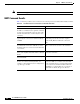

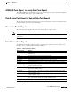
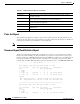
Table Of Contents
- Cisco WAN Modeling Tools User Guide
- Contents
- Related CWM and Switch Documentation
- Obtaining Documentation
- Documentation Feedback
- Cisco Product Security Overview
- Obtaining Technical Assistance
- Obtaining Additional Publications and Information
- Cisco WAN Modeling Tools Overview
- Functionality of the NMT
- Cisco Products Supported by the NMT
- Basic Usage/Charter Functionality
- Gaps
- Data Translation Tools
- System Requirements
- Installing the NMT
- Upgrading the NMT Software
- Starting the NMT
- Removing NMT
- Installing a Cisco WAN Modeling Tools Sub-application
- Removing Sub-applications
- Troubleshooting NMT Installation
- NMT Startup
- NMT Menu Bar
- File Menu
- Display Menu
- Keyboard Commands
- Modeling Processes
- Error Checking
- Troubleshooting NMT
- General Table Information
- Sites Table
- Links Table
- Link Special Cases
- Voice Table
- Data Table
- Bursty Table
- Interface Table
- Feeder Table
- Card Table
- Groups and Network Table
- Nodes Table
- Network Settings
- Model Options
- Feeders
- Obsolete Products
- FastPAD
- Port Concentrator
- Tiered Networks
- Using the Route Command
- AutoRoute
- AutoRoute Least Cost Routing
- PNNI Routing
- Fail Analysis Command
- Build Sites Command
- Optimize Command
- NMT Command Results
- Site Report
- Link Report
- Network Summary Report
- Link Load Report
- ATM & FR Ports Report (or Bursty Data Ports Report)
- Data & Voice Ports Report (or Voice & Data Ports Report)
- Connection Routes Report
- Failed Connections Report
- Parts List Report
- Resource Report/Card Statistics Report
- PNNI Topology Report
- View Summary
- Using the Map Tool
- NMT Map Startup
- Navigating Though a Network View
- Obtaining Link Information - Physical Links
- Obtaining Link Information - Logical Links
- Zooming the Map
- Panning the Map
- Map Color Coding
- Controlling Map Displays in NMT
- NMT Map Main Menu
- Adding New Groups
- Adding Nodes to Existing Groups
- Deleting Groups
- Deleting Nodes or Groups from Existing Groups
- Saving Your Work
- Retrieving Map Data Into NMT
- Using the Map Tool with Fail Analysis
- Using the Map Tool to Analyze Traffic Levels
- Fields Addressed by CET
- Using the CET
- Other CET Commands
- Troubleshooting CET
- Remote CET Extracts
- Translating Between NMT and WANDL Formats
- NMT to Microsoft Excel
- Microsoft Excel to NMT
- Usage Review
- SSI TroubleShooting
- CND PC Import Utilities
- Index

5-3
Cisco WAN Modeling Tools Guide
OL-10426-01, Rev. A0
Chapter 5 NMT Execute Commands
PNNI Routing
The NMT has an Actual Route field with the same format as Preferred Routes. CET Extractions fill in
the Actual Route, which is the tree route of the connection at that time. The Used Preferred Routes option
in Execute Settings determines which set of routes to use with the route command. Preferred routes are
always used in failure analysis commands.
PNNI Routing
When modeling a PNNI Network, the following must be done in the CNF tables:
• Enter Y in the PNNI field of the Site Table to enable PNNI at each site.
• If the PNNI network is a multi group, specify the peer group each site belongs to in the PNNI_PG
field. For multi-level peer group networks, each peer group must be entered in the PNNI domains
table, with its level and parent defined.
• If you want a specific site to be a peer group leader, enter Y in the PGL field for that site. If none
are selected, NMT will select a leader for you.
• Enter Y in the PNNI field of the Link Table to enable PNNI on the links.
• Set the RT_Metrics field in the Bursty Connection table to one of the three types of PNNI routing
algorithms. The choices are AW for administrative weight, CTD for Cell Transfer Delay, or CDV
for Cell Delay Variance.
Note The Model setting PNNI parameters can be adjusted.
Partitioned AutoRoute/PNNI Network
If the modeled network has AutoRoute and PNNI connections, use the steps in the “AutoRoute” and
“PNNI Routing” sections above to configure each portion of the network. If any links are partitioned,
the partitions are defined in the Interface table. The link Port IDs cross reference the interface table
entries. If no partitions are specified, the NMT will optimize the partition based on the connection
demand.
Note MPLS partitions can also be specified. However, the NMT model does not consider traffic on MPLS
partitions.
Table 5-2 Preferred and Directed Route Configuration
Topic Required Settings Comments
Modeling
Preferred or
Directed Routes
Voice, Data, and Bursty Traffic
tables
DR field: Enter Y if the connection
has the directed routing feature,
and N otherwise.
If the Preferred_Route field is left blank or is invalid, this field is
ignored.
Preferred_Route field: Enter a
series of node cross-connects,
separated by equal signs (=).
All site names must be in the Site Table, and each consecutive pair
of sites must have a trunk in the Link Table. The originating and
terminating sites are optional.