
- Cisco WAN Modeling Tools User Guide
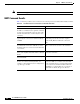

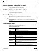
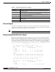
Table Of Contents
- Cisco WAN Modeling Tools User Guide
- Contents
- Related CWM and Switch Documentation
- Obtaining Documentation
- Documentation Feedback
- Cisco Product Security Overview
- Obtaining Technical Assistance
- Obtaining Additional Publications and Information
- Cisco WAN Modeling Tools Overview
- Functionality of the NMT
- Cisco Products Supported by the NMT
- Basic Usage/Charter Functionality
- Gaps
- Data Translation Tools
- System Requirements
- Installing the NMT
- Upgrading the NMT Software
- Starting the NMT
- Removing NMT
- Installing a Cisco WAN Modeling Tools Sub-application
- Removing Sub-applications
- Troubleshooting NMT Installation
- NMT Startup
- NMT Menu Bar
- File Menu
- Display Menu
- Keyboard Commands
- Modeling Processes
- Error Checking
- Troubleshooting NMT
- General Table Information
- Sites Table
- Links Table
- Link Special Cases
- Voice Table
- Data Table
- Bursty Table
- Interface Table
- Feeder Table
- Card Table
- Groups and Network Table
- Nodes Table
- Network Settings
- Model Options
- Feeders
- Obsolete Products
- FastPAD
- Port Concentrator
- Tiered Networks
- Using the Route Command
- AutoRoute
- AutoRoute Least Cost Routing
- PNNI Routing
- Fail Analysis Command
- Build Sites Command
- Optimize Command
- NMT Command Results
- Site Report
- Link Report
- Network Summary Report
- Link Load Report
- ATM & FR Ports Report (or Bursty Data Ports Report)
- Data & Voice Ports Report (or Voice & Data Ports Report)
- Connection Routes Report
- Failed Connections Report
- Parts List Report
- Resource Report/Card Statistics Report
- PNNI Topology Report
- View Summary
- Using the Map Tool
- NMT Map Startup
- Navigating Though a Network View
- Obtaining Link Information - Physical Links
- Obtaining Link Information - Logical Links
- Zooming the Map
- Panning the Map
- Map Color Coding
- Controlling Map Displays in NMT
- NMT Map Main Menu
- Adding New Groups
- Adding Nodes to Existing Groups
- Deleting Groups
- Deleting Nodes or Groups from Existing Groups
- Saving Your Work
- Retrieving Map Data Into NMT
- Using the Map Tool with Fail Analysis
- Using the Map Tool to Analyze Traffic Levels
- Fields Addressed by CET
- Using the CET
- Other CET Commands
- Troubleshooting CET
- Remote CET Extracts
- Translating Between NMT and WANDL Formats
- NMT to Microsoft Excel
- Microsoft Excel to NMT
- Usage Review
- SSI TroubleShooting
- CND PC Import Utilities
- Index

5-5
Cisco WAN Modeling Tools Guide
OL-10426-01, Rev. A0
Chapter 5 NMT Execute Commands
Optimize Command
Optimize Command
The NMT provides several tools for optimizing network models that allow you to create a least-cost
topology with selected links. When you select
Optimize from the Execute menu, the NMT processes
your configuration to design a least-facilities-cost network. The Optimize command eliminates unused
links (links that are not used for routing traffic) from the topology. Although the unused links are
eliminated from the topology, they remain in the links table for possible later use. The process works as
follows:
1. The system calculates all possible topologies and selects the one in which all traffic is routed at the
lowest possible cost. During this process, the Optimizing Topology message box displays a running
tally of the number of topologies tried, the last two most recent costs, and the least cost so far If a
connection fails, the router breaks the routing loop.
Initial Topology is the starting point for building all other topologies that the optimizer can generate
and analyze. It is generated from your specified data, including all sites, links that have positive
values in the ‘Keep’ field and links specified in the preferred routes for the connections.
2. The connections are routed and the complete path is verified. During this process the Routing
Connections message box displays the total number of network connections and maintains a running
tally of the number of connections successfully routed.
3. The program generates several reports. These include informatory messages which describe the
algorithm used to generate the resulting topology (initial, connection based, minimum span tree, or
Link table).
Note If the optimizer fails to find a topology based on initial topology and the minimum span tree
algorithm, it will build a topology based on the Link table. All links marked as removable will
be removed by the optimizer; otherwise, they will be used for connections.
You can stop the optimize process by pressing Escape. If you press Escape during the first step when
the system is calculating all the possible topologies, you are given the option to cancel all processes or
continue with the second process using the best topology found so far.
If the NMT approach to optimization is insufficient, consider using the TPI to translate your network
into WANDL format. WANDL offers several different optimization methods. (See Chapter 12,
“Third-Party Interface.”)
Optimize will write up an informatory message describing which algorithm it used to obtain optimal
topology.
Table 5-3 Optimize Informatory Messages
Message Meaning
Initial Topology Existing Facilities were sufficient to route all
connections. No new links were added.
Connection Based Actual/preferred route information was used to
obtain starting topology.
Minimum Span Tree Minimum span tree algorithm was used to
generate an initial tree topology.
Link Based Links were sorted.