C H A P T E R 42 Configuring PFC QoS This chapter describes how to configure quality of service (QoS) as implemented on the Policy Feature Card (PFC) and Distributed Forwarding Cards (DFCs) on the Cisco 7600 series routers. Note • For complete syntax and usage information for the commands used in this chapter, refer to the Cisco 7600 Series Router Cisco IOS Command Reference at this URL: http://www.cisco.com/univercd/cc/td/doc/product/core/cis7600/software/122sx/cmdref/index.
Chapter 42 Configuring PFC QoS Understanding How PFC QoS Works Understanding How PFC QoS Works The term “PFC QoS” refers to QoS on the Cisco 7600 series router. PFC QoS is implemented on various router components in addition to the PFC and any DFCs.
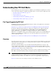
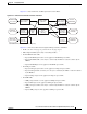
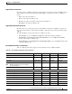
Chapter 42 Configuring PFC QoS Understanding How PFC QoS Works Figure 42-1 PFC QoS Feature Processing Overview MSFC 2 PFC 1 Switching Module 3 120559 Switching Module The PFC QoS features are applied in this order: 1. Ingress port PFC QoS features: – Port trust state—In PFC QoS, trust means to accept as valid and use as the basis of the initial internal DSCP value. Ports are untrusted by default, which sets the initial internal DSCP value to zero.
Chapter 42 Configuring PFC QoS Understanding How PFC QoS Works These figures provide more detail about the relationship between QoS and the router components: • Figure 42-2, Traffic Flow and PFC QoS Features with PFC3 • Figure 42-3, Traffic Flow and PFC QoS Features with PFC2 • Figure 42-4, PFC QoS Features and Component Overview Figure 42-2 shows traffic flow and PFC QoS features with a PFC3.
Chapter 42 Configuring PFC QoS Understanding How PFC QoS Works Figure 42-3 shows traffic flow and PFC QoS features with a PFC2.
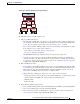
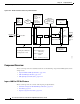
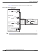
Chapter 42 Configuring PFC QoS Understanding How PFC QoS Works Figure 42-4 PFC QoS Features and Component Overview DSCP map Ingress Port Incoming ToS CoS Q1 Scheduler Q2 Final internal DSCP is mapped to CoS PFC/DFC C l a s s i f i c a t i o n Egress Port Q1 Queueing based on CoS SP Outgoing Q2 Policy Result DSCP CoS rewrite CoS determies queue selection Action - policy map Scheduling rules: WRR, PQ Scheduler operates on WRR, DWRR, SP Trust - DSCP, IP Prec MPLS Exp Q3 WRR DWRR Q4 CoS
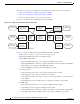
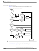
Chapter 42 Configuring PFC QoS Understanding How PFC QoS Works Flowchart of Ingress LAN Port PFC QoS Features Figure 42-5 shows how traffic flows through the ingress LAN port PFC QoS features. Figure 42-5 Ingress LAN Port PFC QoS Features Frame enters switch ISL or 802.
Chapter 42 Configuring PFC QoS Understanding How PFC QoS Works Port Trust In PFC QoS, trust means to accept as valid and use as the basis of the initial internal DSCP value. You can configure ports as untrusted or you can configure them to trust these QoS values: • Layer 2 CoS – A port configured to trust CoS is called a trust CoS port. – Traffic received through a trust CoS port or configured by a policy map to trust CoS is called trust CoS traffic. Not all traffic carries a CoS value. Only ISL, 802.
Chapter 42 Configuring PFC QoS Understanding How PFC QoS Works Supported Policy Feature Cards The policy feature card (PFC) is a daughter card that resides on the supervisor engine. The PFC provides QoS in addition to other functionality.
Chapter 42 Configuring PFC QoS Understanding How PFC QoS Works Figure 42-6 shows how traffic flows through the QoS features on the PFC and DFCs.
Chapter 42 Configuring PFC QoS Understanding How PFC QoS Works Internal DSCP Values During processing, PFC QoS represents the priority of all traffic (including non-IP traffic) with an internal DSCP value.
Chapter 42 Configuring PFC QoS Understanding How PFC QoS Works Port-Based PFC QoS and VLAN-Based PFC QoS You can configure each ingress LAN port for either physical port-based PFC QoS (default) or VLAN-based PFC QoS and attach a policy map to the selected interface.
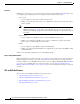
Chapter 42 Configuring PFC QoS Understanding How PFC QoS Works Flowchart of PFC QoS Egress LAN Port Features Figure 42-7 shows how traffic flows through the QoS features on egress LAN ports. Figure 42-7 Egress LAN Port Scheduling, Congestion Avoidance, and Marking From PFC or MSFC PFC3 only Egress queues and drop thresholds IP traffic Yes from PFC? Yes Write ToS byte into packet No No ISL or 802.
Chapter 42 Configuring PFC QoS Understanding How PFC QoS Works Egress DSCP Mutation with a PFC3 With a PFC3, you can configure 15 egress DSCP mutation maps to mutate the internal DSCP value before it is written in the egress ToS byte. You can attach egress DSCP mutation maps to any interface that PFC QoS supports. Note • If you configure egress DSCP mutation, PFC QoS does not derive the egress CoS value from the mutated DSCP value. • The PFC2 does not support egress DSCP mutation.
Chapter 42 Configuring PFC QoS Understanding How PFC QoS Works On interfaces where egress ACL support for remarked DSCP is configured, the PFC3 processes each QoS-filtered IP packet twice: once to apply ingress PFC QoS and once to apply egress PFC QoS.
Chapter 42 Configuring PFC QoS Understanding How PFC QoS Works Understanding Classification and Marking The following sections describe where and how classification and marking occur on the Cisco 7600 series routers: • Classification and Marking at Trusted and Untrusted Ingress Ports, page 42-16 • Classification and Marking at Ingress OSM Ports, page 42-17 • Classification and Marking on the PFC Using Service Policies and Policy Maps, page 42-18 • Classification and Marking on the MSFC, page 42-19
Chapter 42 Configuring PFC QoS Understanding How PFC QoS Works These sections describe classification and marking at trusted ingress ports: • Ingress Classification and Marking at Trust CoS LAN Ports, page 42-17 • Ingress Classification and Marking at Trust IP Precedence Ports, page 42-17 • Ingress Classification and Marking at Trust DSCP Ports, page 42-17 Ingress Classification and Marking at Trust CoS LAN Ports You should configure LAN ports to trust CoS only if they receive traffic that carries
Chapter 42 Configuring PFC QoS Understanding How PFC QoS Works • Trust CoS (CoS is always zero for POS and ATM OSM ports because the port CoS value is not configurable on POS and ATM OSM ports.
Chapter 42 Configuring PFC QoS Understanding How PFC QoS Works Classification and Marking on the MSFC PFC QoS sends IP traffic to the MSFC with the final internal DSCP values. CoS is equal to IP precedence in all traffic sent from the MSFC to egress ports.
Chapter 42 Configuring PFC QoS Understanding How PFC QoS Works The PFC2 supports only ingress PFC QoS, which includes ingress policing. The PFC3 supports both ingress and egress PFC QoS, which includes ingress and egress policing. Traffic shaping is supported on some WAN modules. For more information about traffic shaping on the OSM and FlexWAN modules, refer to the OSM and FlexWAN documentation at this location: http://www.cisco.com/univercd/cc/td/doc/product/core/cis7600/cfgnotes/index.
Chapter 42 Configuring PFC QoS Understanding How PFC QoS Works Microflow Policers PFC QoS applies the bandwidth limit specified in a microflow policer separately to each flow in matched traffic. For example, if you configure a microflow policer to limit the TFTP traffic to 1 Mbps on VLAN 1 and VLAN 3, then 1 Mbps is allowed for each flow in VLAN 1 and 1 Mbps for each flow in VLAN 3.
Chapter 42 Configuring PFC QoS Understanding How PFC QoS Works With a PFC3, policing uses the Layer 2 frame size. With a PFC2, policing uses the Layer 3 packet size. You specify the bandwidth utilization limit as a committed information rate (CIR). You can also specify a higher peak information rate (PIR). Packets that exceed a rate are “out of profile” or “nonconforming.
Chapter 42 Configuring PFC QoS Understanding How PFC QoS Works The Cisco 7600 series router LAN modules support the following types of scheduling algorithms between queues: • Shaped round robin (SRR)—SRR allows a queue to use only the allocated bandwidth. • Deficit weighted round robin (DWRR)—DWRR keeps track of any lower-priority queue under-transmission caused by traffic in a higher-priority queue and compensates in the next round.
Chapter 42 Configuring PFC QoS Understanding How PFC QoS Works Figure 42-10 illustrates the drop thresholds for a 1q4t ingress LAN port. Drop thresholds in other configurations function similarly.
Chapter 42 Configuring PFC QoS Understanding How PFC QoS Works • 1p1q0t indicates: – One strict-priority queue – One standard queue with no configurable threshold (effectively a tail-drop threshold at 100 percent).
Chapter 42 Configuring PFC QoS Understanding How PFC QoS Works • 1p7q8t indicates the following: – One strict-priority queue – Seven standard queues, each with eight thresholds, each threshold configurable as either WRED-drop or tail-drop Module to Queue Type Mappings The following tables show the module to queue structure mapping: • Supervisor Engine Module QoS Queue Structures • Ethernet and Fast Ethernet Module Queue Structures • Gigabit and 10/100/1000 Ethernet Modules • 10 Gigabit Ethernet
Chapter 42 Configuring PFC QoS Understanding How PFC QoS Works Table 42-3 Ethernet and Fast Ethernet Module Queue Structures (continued) Modules Ingress Queue and Drop Thresholds Ingress Queue Scheduler Egress Queue and Drop Thresholds Egress Queue Scheduler Total Buffer Ingress Size Buffer Size Egress Buffer Size WS-X6324-100FX-MM 1q4t — 2q2t WRR 128 KB 16 KB 112 KB 64 KB 8 KB 56 KB 128 KB 16 KB 112 KB WS-X6324-100FX-SM WS-X6348-RJ-45 WS-X6348-RJ-45V WS-X6348-RJ-21V WS-X6224-100FX-M
Chapter 42 Configuring PFC QoS PFC QoS Default Configuration Table 42-4 Gigabit and 10/100/1000 Ethernet Modules Modules Ingress Queue and Drop Thresholds Ingress Queue Scheduler Egress Queue and Drop Thresholds Egress Queue Scheduler Total Buffer Ingress Size Buffer Size Egress Buffer Size WS-X6516-GBIC 1p1q4t — 1p2q2t WRR 512 KB 73 KB 439 KB WS-X6516A-GBIC WRR 1 MB 135 KB 946 KB WS-X6516-GE-TX WRR 512 KB 73 KB 439 KB WS-X6408-GBIC 1q4t — 2q2t WRR 80 KB 432 KB WS-X6408A-
Chapter 42 Configuring PFC QoS PFC QoS Default Configuration PFC QoS Global Settings The following global PFC QoS settings apply: Feature Default Value PFC QoS global enable state Disabled PFC QoS port enable state Enabled when PFC QoS is globally enabled Port CoS value 0 Microflow policing Enabled IntraVLAN microflow policing Disabled Port-based or VLAN-based PFC QoS Port-based Received CoS to initial internal DSCP map (initial internal DSCP set from received CoS values) CoS 0 = DSCP 0 CoS
Chapter 42 Configuring PFC QoS PFC QoS Default Configuration Default Values With PFC QoS Enabled These sections list the default values that apply when PFC QoS is enabled: Note • Receive-Queue Limits, page 42-30 • Transmit-Queue Limit s, page 42-30 • Bandwidth Allocation Ratios, page 42-31 • Default Drop-Threshold Percentages and CoS Value Mappings, page 42-31 The ingress LAN port trust state defaults to untrusted with QoS enabled.
Chapter 42 Configuring PFC QoS PFC QoS Default Configuration Feature Default Value 1p7q4t Standard queue 1 (lowest priority): 50% Standard queue 2: 20% Standard queue 3: 15% Standard queues 4 through 7: 0% Strict priority 15% 1p7q8t Standard queue 1 (lowest priority): 50% Standard queue 2: 20% Standard queue 3: 15% Standard queues 4 through 7: 0% Strict priority 15% Bandwidth Allocation Ratios Feature Default Value 2q8t 90:10 8q4t 90:0:0:0:0:0:0:10 8q8t 90:0:0:0:0:0:0:10 1p3q8t 22:33:45 1p
Chapter 42 Configuring PFC QoS PFC QoS Default Configuration Note • 1p2q2t Transmit Queues, page 42-42 • 1p3q8t Transmit Queues, page 42-43 • 1p7q4t Transmit Queues, page 42-44 • 1p7q8t Transmit Queues, page 42-47 • 1p3q1t Transmit Queues, page 42-48 • 1p2q1t Transmit Queues, page 42-49 The receive queue values shown are the values in effect when the port is configured to trust CoS or DSCP. When the port is untrusted, the receive queue values are the same as when QoS is globally disabled.
Chapter 42 Configuring PFC QoS PFC QoS Default Configuration 1p1q4t Receive Queues Feature Standard receive queue Default Value Threshold 1 CoS 0 and 1 Tail-drop 50% WRED-drop Not supported Threshold 2 CoS 2 and 3 Tail-drop 60% WRED-drop Not supported Threshold 3 CoS 4 Tail-drop 80% WRED-drop Not supported Threshold 4 CoS 6 and 7 Tail-drop 100% WRED-drop Not supported Strict-priority receive queue CoS 5 Tail-drop 100% (nonconfigurable) 1p1q0t Receive Queues Feature Default Val
Chapter 42 Configuring PFC QoS PFC QoS Default Configuration 1p1q8t Receive Queues Feature Standard receive queue Default Value Threshold 1 CoS 0 Tail-drop Disabled; 70% WRED-drop Enabled; 40% low, 70% high Threshold 2 CoS 1 Tail-drop Disabled; 70% WRED-drop Enabled; 40% low, 70% high Threshold 3 CoS 2 Tail-drop Disabled; 80% WRED-drop Enabled; 50% low, 80% high Threshold 4 CoS 3 Tail-drop Disabled; 80% WRED-drop Enabled; 50% low, 80% high Threshold 5 CoS 4 Tail-drop Disabled; 9
Chapter 42 Configuring PFC QoS PFC QoS Default Configuration 1q8t Receive Queues Feature Standard receive queue Default Value Threshold 1 CoS 0 Tail-drop 50% WRED-drop Not supported Threshold 2 CoS None Tail-drop 50% WRED-drop Not supported Threshold 3 CoS 1, 2, 3, 4 Tail-drop 60% WRED-drop Not supported Threshold 4 CoS None Tail-drop 60% WRED-drop Not supported Threshold 5 CoS 6 and 7 Tail-drop 80% WRED-drop Not supported Threshold 6 CoS None Tail-drop 80% WRED-drop Not su
Chapter 42 Configuring PFC QoS PFC QoS Default Configuration 2q8t Receive Queues Feature Standard receive queue 1 (low priority) Default Value Threshold 1 CoS 0 and 1 Tail-drop 70% WRED-drop Not supported Threshold 2 CoS 2 and 3 Tail-drop 80% WRED-drop Not supported Threshold 3 CoS 4 Tail-drop 90% WRED-drop Not supported Threshold 4 CoS 6 and 7 Tail-drop 100% WRED-drop Not supported Thresholds 5–8 CoS Tail-drop None 100% WRED-drop Not supported Standard receive queue 2 (high prior
Chapter 42 Configuring PFC QoS PFC QoS Default Configuration 8q4t Receive Queues Feature Standard receive queue 1 (lowest priority) Default Value Threshold 1 CoS 0 and 1 DSCP 0–9, 11, 13, 15–17, 19, 21, 23, 25, 27, 29, 31, 33, 39, 41–45, 47 Tail-drop Disabled; 70% WRED-drop Enabled; 40% low, 70% high Threshold 2 CoS 2 and 3 DSCP Tail-drop Disabled; 80% WRED-drop Enabled; 40% low, 80% high Threshold 3 CoS 4 DSCP Tail-drop Disabled; 90% WRED-drop Enabled; 50% low, 90% high Threshold 4 Co
Chapter 42 Configuring PFC QoS PFC QoS Default Configuration Feature (continued) Standard receive queue 3 (intermediate priority) Default Value Threshold 1 CoS None DSCP 22 Tail-drop Enabled; 100% WRED-drop Disabled; 100% low, 100% high Threshold 2 CoS None DSCP 20 Tail-drop Enabled; 100% WRED-drop Disabled; 100% low, 100% high Threshold 3 CoS None DSCP 18 Tail-drop Enabled; 100% WRED-drop Disabled; 100% low, 100% high Threshold 4 CoS None DSCP None Tail-drop Enabled; 100% WR
Chapter 42 Configuring PFC QoS PFC QoS Default Configuration Feature (continued) Standard receive queue 5 (intermediate priority) Default Value Threshold 1 CoS None DSCP 32, 34–38 Tail-drop Enabled; 100% WRED-drop Disabled; 100% low, 100% high Threshold 2 CoS None DSCP None Tail-drop Enabled; 100% WRED-drop Disabled; 100% low, 100% high Threshold 3 CoS None DSCP None Tail-drop Enabled; 100% WRED-drop Disabled; 100% low, 100% high Threshold 4 CoS None DSCP None Tail-drop Enabled
Chapter 42 Configuring PFC QoS PFC QoS Default Configuration Feature (continued) Standard receive queue 7 (intermediate priority) Default Value Threshold 1 CoS None DSCP None Tail-drop Enabled; 100% WRED-drop Disabled; 100% low, 100% high Threshold 2 CoS None DSCP None Tail-drop Enabled; 100% WRED-drop Disabled; 100% low, 100% high Threshold 3 CoS None DSCP None Tail-drop Enabled; 100% WRED-drop Disabled; 100% low, 100% high Threshold 4 CoS None DSCP None Tail-drop Enabled; 10
Chapter 42 Configuring PFC QoS PFC QoS Default Configuration 8q8t Receive Queues Feature Default Value Standard receive queue 1 (lowest priority) Threshold 1 CoS 0 and 1 Tail-drop Disabled; 70% WRED-drop Enabled; 40% low, 70% high Threshold 2 CoS 2 and 3 Tail-drop Disabled; 80% WRED-drop Enabled; 40% low, 80% high Threshold 3 CoS 4 Tail-drop Disabled; 90% WRED-drop Enabled; 50% low, 90% high Threshold 4 CoS 6 and 7 Tail-drop Disabled; 100% WRED-drop Enabled; 50% low, 100% high Thre
Chapter 42 Configuring PFC QoS PFC QoS Default Configuration Feature Standard transmit queue 2 (high priority) Default Value Threshold 1 CoS 4 and 5 Tail-drop 80% WRED-drop Not supported Threshold 2 CoS 6 and 7 Tail-drop 100% WRED-drop Not supported 1p2q2t Transmit Queues Feature Standard transmit queue 1 (low priority) Default Value Threshold 1 CoS 0 and 1 Tail-drop Not supported WRED-drop 40% low, 70% high Threshold 2 CoS 2 and 3 Tail-drop Not supported WRED-drop 70% low, 100% h
Chapter 42 Configuring PFC QoS PFC QoS Default Configuration 1p3q8t Transmit Queues Feature Default Value Standard transmit queue 1 (lowest priority) Threshold 1 CoS 0 Tail-drop Disabled; 70% WRED-drop Enabled; 40% low, 70% high Threshold 2 CoS 1 Tail-drop Disabled; 100% WRED-drop Enabled; 70% low, 100% high Threshold 3 CoS None Tail-drop Disabled; 100% WRED-drop Enabled; 70% low, 100% high Threshold 4 CoS None Tail-drop Disabled; 100% WRED-drop Enabled; 70% low, 100% high Threshol
Chapter 42 Configuring PFC QoS PFC QoS Default Configuration 1p7q4t Transmit Queues Feature Standard receive queue 1 (lowest priority) Default Value Threshold 1 CoS 0 and 1 DSCP 0–9, 11, 13, 15–17, 19, 21, 23, 25, 27, 29, 31, 33, 39, 41–45, 47 Tail-drop Disabled; 70% WRED-drop Enabled; 40% low, 70% high Threshold 2 CoS 2 and 3 DSCP Tail-drop Disabled; 100% WRED-drop Enabled; 70% low, 100% high Threshold 3 CoS 4 DSCP Tail-drop Disabled; 100% WRED-drop Enabled; 70% low, 100% high Thresho
Chapter 42 Configuring PFC QoS PFC QoS Default Configuration Feature (continued) Standard receive queue 3 (intermediate priority) Default Value Threshold 1 CoS None DSCP 22 Tail-drop Disabled; 100% WRED-drop Enabled; 70% low, 100% high Threshold 2 CoS None DSCP 20 Tail-drop Disabled; 100% WRED-drop Enabled; 70% low, 100% high Threshold 3 CoS None DSCP 18 Tail-drop Disabled; 100% WRED-drop Enabled; 70% low, 100% high Threshold 4 CoS None DSCP None Tail-drop Disabled; 100% WRED-
Chapter 42 Configuring PFC QoS PFC QoS Default Configuration Feature (continued) Standard receive queue 5 (intermediate priority) Default Value Threshold 1 CoS None DSCP 32, 34–38 Tail-drop Enabled; 100% WRED-drop Disabled; 100% low, 100% high Threshold 2 CoS None DSCP None Tail-drop Enabled; 100% WRED-drop Disabled; 100% low, 100% high Threshold 3 CoS None DSCP None Tail-drop Enabled; 100% WRED-drop Disabled; 100% low, 100% high Threshold 4 CoS None DSCP None Tail-drop Enable
Chapter 42 Configuring PFC QoS PFC QoS Default Configuration Feature (continued) Default Value Standard receive queue 7 (intermediate priority) Threshold 1 CoS None DSCP None Tail-drop Enabled; 100% WRED-drop Disabled; 100% low, 100% high Threshold 2 CoS None DSCP None Tail-drop Enabled; 100% WRED-drop Disabled; 100% low, 100% high Threshold 3 CoS None DSCP None Tail-drop Enabled; 100% WRED-drop Disabled; 100% low, 100% high Threshold 4 CoS None DSCP None Tail-drop Enabled; 1
Chapter 42 Configuring PFC QoS PFC QoS Default Configuration Feature (continued) Standard transmit queue 2 (intermediate priority) Default Value Threshold 1 CoS 2 Tail-drop Disabled; 70% WRED-drop Enabled; 40% low, 70% high Threshold 2 CoS 3 and 4 Tail-drop Disabled; 100% WRED-drop Enabled; 70% low, 100% high Thresholds 3–8 CoS Tail-drop None Disabled; 100% WRED-drop Enabled; 70% low, 100% high Standard transmit queue 3 (intermediate priority) Threshold 1 CoS 6 and 7 Tail-drop Disabled;
Chapter 42 Configuring PFC QoS PFC QoS Configuration Guidelines and Restrictions 1p2q1t Transmit Queues Feature Default Value Standard transmit queue 1 (lowest priority) Threshold 1 CoS 0, 1, 2, and 3 Tail-drop Not supported WRED-drop Enabled; 70% low, 100% high Standard transmit queue 3 (high priority) Threshold 1 CoS 4, 6, and 7 Tail-drop Not supported WRED-drop Enabled; 70% low, 100% high Strict-priority transmit queue CoS 5 Tail-drop 100% (nonconfigurable) Default Values With PFC Q
Chapter 42 Configuring PFC QoS PFC QoS Configuration Guidelines and Restrictions General Guidelines • The match ip precedence and match ip dscp commands filter only IPv4 traffic. • In Release 12.2(18)SXE and later releases, the match precedence and match dscp commands filter IPv4 and IPv6 traffic. • In Release 12.2(18)SXE and later releases, the set ip dscp and set ip precedence commands are saved in the configuration file as set dscp and set precedence commands. • In Release 12.
Chapter 42 Configuring PFC QoS PFC QoS Configuration Guidelines and Restrictions • For these commands, PFC QoS applies identical configuration to all LAN ports controlled by the same application-specific integrated circuit (ASIC): – rcv-queue random-detect – rcv-queue queue-limit – wrr-queue queue-limit – wrr-queue bandwidth (except Gigabit Ethernet LAN ports) – priority-queue cos-map – rcv-queue cos-map – wrr-queue cos-map – wrr-queue threshold – rcv-queue threshold – wrr-queue random-detect – wrr-queue
Chapter 42 Configuring PFC QoS PFC QoS Configuration Guidelines and Restrictions • The QoS features implemented in the port ASICs (queue architecture and dequeuing algorithms) support IPv4 and IPv6 traffic. • The PFC3 supports IPv6 named extended ACLs and named standard ACLs. • In Release 12.2(18)SXE and later releases, the PFC3 supports the match protocol ipv6 command.
Chapter 42 Configuring PFC QoS PFC QoS Configuration Guidelines and Restrictions Class Map Command Restrictions • With Release 12.2(18)SXE and later releases, PFC QoS supports the match any class map command. • PFC QoS supports class maps that contain a single match command.
Chapter 42 Configuring PFC QoS PFC QoS Configuration Guidelines and Restrictions CIR and PIR Rate Value Range Granularity 4194305 to 8388608 (8 Mbs) 131072 (128 Kb) 8388609 to 16777216 (16 Mbs) 262144 (256 Kb) 16777217 to 33554432 (32 Mbs) 524288 (512 Kb) 33554433 to 67108864 (64 Mbs) 1048576 (1 Mb) 67108865 to 134217728 (128 Mbs) 2097152 (2 Mb) 134217729 to 268435456 (256 Mbs) 4194304 (4 Mb) 268435457 to 536870912 (512 Mbs) 8388608 (8 Mb) 536870913 to 1073741824 (1 Gps) 16777216 (16 Mb)
Chapter 42 Configuring PFC QoS Configuring PFC QoS IP Precedence and DSCP Values 3-bit IP Precedence 6 MSb1 of ToS 0 0 0 0 0 0 0 0 0 0 0 0 0 0 0 0 0 0 0 0 0 0 0 0 0 0 0 0 0 1 1 1 1 0 0 1 1 0 0 1 1 0 1 0 1 0 1 0 1 1 0 0 0 0 0 0 0 0 0 0 0 0 0 0 0 0 1 1 1 1 1 1 1 1 0 0 0 0 1 1 1 1 0 0 1 1 0 0 1 1 2 0 0 0 0 0 0 0 0 1 1 1 1 1 1 1 1 0 0 0 0 0 0 0 0 0 0 0 0 1 1 1 1 3 0 0 0 0 0 0 0 0 1 1 1 1 1 1 1 1 1 1 1 1 1 1 1 1 0 0 0 0 1 1 1 1 8 7 6 3-bit IP Precedence 6 MSb1 of ToS 0 1 2 3 4 5 6 7
Chapter 42 Configuring PFC QoS Configuring PFC QoS Note • Enabling Microflow Policing of Bridged Traffic, page 42-59 • Enabling VLAN-Based PFC QoS on Layer 2 LAN Ports, page 42-60 • Enabling Egress ACL Support for Remarked DSCP, page 42-61 • Creating Named Aggregate Policers, page 42-61 • Configuring a PFC QoS Policy, page 42-64 • Configuring Egress DSCP Mutation on a PFC3, page 42-82 • Configuring Ingress CoS Mutation on IEEE 802.
Chapter 42 Configuring PFC QoS Configuring PFC QoS IP packets with COS changed by policing: 59998 Non-IP packets with COS changed by policing: 0 Router# Enabling Ignore Port Trust In Release 12.2(18)SXF5 and later releases, the ignore port trust feature allows an ingress policy to apply a configured IP precedence or DSCP value to any traffic, rather than only to untrusted traffic.
Chapter 42 Configuring PFC QoS Configuring PFC QoS Configuring DSCP Transparency Note • In addition to support for other IP traffic, the PFC3B and PFC3BXL support the no mls qos rewrite ip dscp command for MPLS traffic, traffic in IP in IP tunnels, and traffic in GRE tunnels. • The PFC3A supports the no mls qos rewrite ip dscp command for all IP traffic except MPLS traffic, traffic in IP in IP tunnels, and traffic in GRE tunnels.
Chapter 42 Configuring PFC QoS Configuring PFC QoS Note The router applies the port CoS value to untagged ingress traffic and to traffic that is received through ports that cannot be configured to trust CoS.
Chapter 42 Configuring PFC QoS Configuring PFC QoS Enabling VLAN-Based PFC QoS on Layer 2 LAN Ports Note • With a PFC2, PFC QoS does not support VLAN-based QoS with DFCs installed. • With a PFC3, PFC QoS supports VLAN-based QoS with DFC3s installed. • With a PFC3, you can attach policy maps to Layer 3 interfaces for application of PFC QoS to egress traffic. VLAN-based or port-based PFC QoS on Layer 2 ports is not relevant to application of PFC QoS to egress traffic on Layer 3 interfaces.
Chapter 42 Configuring PFC QoS Configuring PFC QoS Enabling Egress ACL Support for Remarked DSCP To enable egress ACL support for remarked DSCP on an ingress interface, perform this task: Command Purpose Step 1 Router(config)# interface {{vlan vlan_ID} | {type1 slot/port} | {port-channel number}} Selects the ingress interface to configure.
Chapter 42 Configuring PFC QoS Configuring PFC QoS When creating a named aggregate policer, note the following information: • Aggregate policing works independently on each DFC-equipped switching module and independently on the PFC, which supports any non-DFC-equipped switching modules. Aggregate policing does not combine flow statistics from different DFC-equipped switching modules.
Chapter 42 Configuring PFC QoS Configuring PFC QoS • The valid range of values for the pir bits_per_second parameter is as follows: – Minimum—32 kilobits per second, entered as 32000 (the value cannot be smaller than the CIR bits_per_second parameters) – Maximum with Release 12.2(18)SXE and later releases: 10 gigabits per second, entered as 10000000000 – Maximum with releases earlier than Release 12.
Chapter 42 Configuring PFC QoS Configuring PFC QoS Note When you apply both ingress policing and egress policing to the same traffic, both the input policy and the output policy must either mark down traffic or drop traffic. PFC QoS does not support ingress markdown with egress drop or ingress drop with egress markdown.
Chapter 42 Configuring PFC QoS Configuring PFC QoS PFC QoS Policy Configuration Overview Note To mark traffic without limiting bandwidth utilization, create a policer that uses the transmit keywords for both conforming and nonconforming traffic. These commands configure traffic classes and the policies to be applied to those traffic classes and attach the policies to ports: • access-list (Optional for IP traffic. You can filter IP traffic with class-map commands.
Chapter 42 Configuring PFC QoS Configuring PFC QoS • class-map (optional)—Enter the class-map command to define one or more traffic classes by specifying the criteria by which traffic is classified. • policy-map—Enter the policy-map command to define the following: – Policy map class trust mode – Aggregate policing and marking – Microflow policing and marking • service-policy—Enter the service-policy command to attach a policy map to an interface.
Chapter 42 Configuring PFC QoS Configuring PFC QoS When configuring protocol-independent MAC ACL filtering, note the following information: • Do not configure protocol-independent MAC ACL filtering on VLAN interfaces where you have configured an IP address. • Do not configure protocol-independent MAC ACL filtering with microflow policing when the permitted traffic would be bridged or Layer 3 switched in hardware by the PFC3BXL.
Chapter 42 Configuring PFC QoS Configuring PFC QoS To disable VLAN-based QoS filtering in MAC ACLs, perform this task: Command Purpose Router(config)# no mac packet-classify use vlan Disables VLAN-based QoS filtering in MAC ACLs. Configuring MAC ACLs You can configure named ACLs that filter IPX, DECnet, AppleTalk, VINES, or XNS traffic based on MAC addresses (IPX filtering with a MAC ACL is supported only with a PFC3). In Release 12.
Chapter 42 Configuring PFC QoS Configuring PFC QoS • ACL entries are scanned in the order you enter them. The first matching entry is used. To improve performance, place the most commonly used entries near the beginning of the ACL. • An implicit deny any any entry exists at the end of an ACL unless you include an explicit permit any any entry at the end of the list. • All new entries to an existing list are placed at the end of the list. You cannot add entries to the middle of a list.
Chapter 42 Configuring PFC QoS Configuring PFC QoS With a PFC3 and Release 12.2(18)SXD and later releases, you can configure named ACLs that filter ARP traffic (EtherType 0x0806) for QoS. To configure an ARP ACL for QoS filtering, perform this task: Step 1 Step 2 Command Purpose Router(config)# arp access-list list_name Configures an ARP ACL for QoS filtering. Router(config)# no arp access-list list_name Deletes an ARP ACL.
Chapter 42 Configuring PFC QoS Configuring PFC QoS Class Map Filtering Guidelines and Restrictions When configuring class map filtering, follow these guidelines and restrictions: • With Release 12.2(18)SXE and later releases, PFC QoS supports multiple match criteria in class maps configured with the match-any keywords. • With releases earlier than Release 12.2(18)SXE, PFC QoS supports class maps that contain a single match command. • With Release 12.
Chapter 42 Configuring PFC QoS Configuring PFC QoS Command Purpose Router (config-cmap)# match protocol ipv6 (Optional—for IPv6 traffic) Configures the class map to filter IPv6 traffic. Router (config-cmap)# no match protocol ipv6 Clears IPv6 filtering. Router (config-cmap)# match precedence ipp_value1 [ipp_value2 [ipp_valueN]] (Optional—for IPv4 or IPv6 traffic) Configures the class map to filter based on up to eight IP precedence values.
Chapter 42 Configuring PFC QoS Configuring PFC QoS This example shows how to verify the configuration: Router# show class-map ipp5 Class Map match-all ipp5 (id 1) Match ip precedence 5 Configuring a Policy Map You can attach only one policy map to an interface. Policy maps can contain one or more policy map classes, each with different policy map commands. Configure a separate policy map class in the policy map for each type of traffic that an interface receives.
Chapter 42 Configuring PFC QoS Configuring PFC QoS Creating a Policy Map Class and Configuring Filtering To create a policy map class and configure it to filter with a class map, perform this task: Command Purpose Router(config-pmap)# class class_name Creates a policy map class and configures it to filter with a class map. Note Router(config-pmap)# no class class_name PFC QoS supports class maps that contain a single match command. Clears use of the class map.
Chapter 42 Configuring PFC QoS Configuring PFC QoS These sections describe policy map class action configuration: • Configuring Policy Map Class Marking, page 42-75 • Configuring the Policy Map Class Trust State, page 42-75 • Configuring Policy Map Class Policing, page 42-76 Configuring Policy Map Class Marking In Release 12.2(18)SXF5 and later releases, when the ignore port trust feature is enabled, PFC QoS supports policy map class marking for all traffic with set policy map class commands.
Chapter 42 Configuring PFC QoS Configuring PFC QoS Configuring Policy Map Class Policing When you configure policy map class policing, note the following information: • PFC QoS does not support the set-qos-transmit policer keyword. • PFC QoS does not support the set-dscp-transmit or set-prec-transmit keywords as arguments to the exceed-action keyword. • PFC QoS does not detect the use of unsupported keywords until you attach a policy map to an interface.
Chapter 42 Configuring PFC QoS Configuring PFC QoS When configuring a per-interface policer, note the following information: • Aggregate policing works independently on each DFC-equipped switching module and independently on the PFC, which supports any non-DFC-equipped switching modules. Aggregate policing does not combine flow statistics from different DFC-equipped switching modules.
Chapter 42 Configuring PFC QoS Configuring PFC QoS Note • The flowmask requirements of microflow policing, NetFlow, and NetFlow data export (NDE) might conflict. The valid range of values for the CIR bits_per_second parameter is as follows: – Minimum—32 kilobits per second, entered as 32000 – Maximum with Release 12.2(18)SXE and later releases: 10 gigabits per second, entered as 10000000000 – Maximum with releases earlier than Release 12.
Chapter 42 Configuring PFC QoS Configuring PFC QoS • (Optional) For traffic that exceeds the CIR, you can specify an exceed action as follows: – For marking without policing, you can enter the transmit keyword to transmit all matched out-of-profile traffic. – The default exceed action is drop, except with a maximum_burst_bytes parameter (drop is not supported with a maximum_burst_bytes parameter). Note When the exceed action is drop, PFC QoS ignores any configured violate action.
Chapter 42 Configuring PFC QoS Configuring PFC QoS This example shows how to verify the configuration: Router# show policy-map max-pol-ipp5 Policy Map max-pol-ipp5 class ipp5 class ipp5 police flow 10000000 10000 conform-action set-prec-transmit 6 exceed-action policed-dscp-transmit trust precedence police 2000000000 2000000 2000000 conform-action set-prec-transmit 6 exceed-action policed-dscp-transmit Router# Attaching a Policy Map to an Interface To attach a policy map to an interface, perform this ta
Chapter 42 Configuring PFC QoS Configuring PFC QoS • Aggregate policing works independently on each DFC-equipped switching module and independently on the PFC, which supports any non-DFC-equipped switching modules. Aggregate policing does not combine flow statistics from different DFC-equipped switching modules. You can display aggregate policing statistics for each DFC-equipped switching module and for the PFC and any non-DFC-equipped switching modules supported by the PFC.
Chapter 42 Configuring PFC QoS Configuring PFC QoS Configuring Egress DSCP Mutation on a PFC3 Note The PFC2 does not support egress DSCP mutation.
Chapter 42 Configuring PFC QoS Configuring PFC QoS Note In the DSCP mutation map displays, the marked-down DSCP values are shown in the body of the matrix; the first digit of the original DSCP value is in the column labeled d1 and the second digit is in the top row. In the example shown, DSCP 30 maps to DSCP 08.
Chapter 42 Configuring PFC QoS Configuring PFC QoS Ingress CoS Mutation Configuration Guidelines and Restrictions When configuring ingress CoS mutation, follow these guidelines and restrictions: • Release 12.2(17b)SXA and later releases support ingress CoS mutation on WS-X6704-10GE, WS-X6748-SFP, WS-X6724-SFP, and WS-X6748-GE-TX switching modules. • Ports that are not configured as IEEE 802.1Q tunnel ports do not support ingress CoS mutation.
Chapter 42 Configuring PFC QoS Configuring PFC QoS Configuring Ingress CoS Mutation Maps To configure an ingress CoS mutation map, perform this task: Command Purpose Router(config)# mls qos map cos-mutation mutation_map_name mutated_cos1 mutated_cos2 mutated_cos3 mutated_cos4 mutated_cos5 mutated_cos6 mutated_cos7 mutated_cos8 Configures an ingress CoS mutation map. You must enter 8 mutated CoS values to which PFC QoS maps ingress CoS values 0 through 7.
Chapter 42 Configuring PFC QoS Configuring PFC QoS This example shows how to attach the ingress CoS mutation map named testmap to Gigabit Ethernet port 1/1: Router# configure terminal Enter configuration commands, one per line. End with CNTL/Z.
Chapter 42 Configuring PFC QoS Configuring PFC QoS This example shows how to verify the configuration: Router# show mls qos maps | begin Cos-dscp map Cos-dscp map: cos: 0 1 2 3 4 5 6 7 ---------------------------------dscp: 0 1 2 3 4 5 6 7 <...Output Truncated...
Chapter 42 Configuring PFC QoS Configuring PFC QoS Command Purpose Step 2 Router(config)# end Exits configuration mode. Step 3 Router# show mls qos maps Verifies the configuration. When configuring a DSCP markdown map, note the following information: • You can enter the normal-burst keyword to configure the markdown map used by the exceed-action policed-dscp-transmit keywords.
Chapter 42 Configuring PFC QoS Configuring PFC QoS Maximum Burst Policed-dscp map: d1 : d2 0 1 2 3 4 5 6 7 8 9 ------------------------------------0 : 00 01 02 03 04 05 06 07 08 09 1 : 10 11 12 13 14 15 16 17 18 19 2 : 20 21 22 23 24 25 26 27 28 29 3 : 30 31 32 33 34 35 36 37 38 39 4 : 40 41 42 43 44 45 46 47 48 49 5 : 50 51 52 53 54 55 56 57 58 59 6 : 60 61 62 63 <...Output Truncated...
Chapter 42 Configuring PFC QoS Configuring PFC QoS This example shows how to verify the configuration: Router# show mls qos map | begin Dscp-cos map Dscp-cos map: d1 : d2 0 1 2 3 4 5 6 7 8 9 ------------------------------------0 : 00 00 00 00 00 00 00 00 00 01 1 : 01 01 01 01 01 01 00 02 02 02 2 : 02 02 02 02 00 03 03 03 03 03 3 : 03 03 00 04 04 04 04 04 04 04 4 : 00 05 05 05 05 05 05 05 00 06 5 : 06 06 06 06 00 06 07 07 07 07 6 : 07 07 07 07 <...Output Truncated...
Chapter 42 Configuring PFC QoS Configuring PFC QoS • The mls qos trust cos command enables CoS-based receive-queue drop thresholds. To avoid dropping traffic because of inconsistent CoS values, configure ports with the mls qos trust cos command only when the received traffic is ISL or 802.1Q frames carrying CoS values that you know to be consistent with network policy. • With Release 12.2(17b)SXA and later releases, you can configure IEEE 8021.
Chapter 42 Configuring PFC QoS Configuring PFC QoS To configure the CoS value for an ingress LAN port, perform this task: Command Purpose Step 1 Router(config)# interface {{type1 slot/port} | {port-channel number}} Selects the interface to configure. Step 2 Router(config-if)# mls qos cos port_cos Configures the ingress LAN port CoS value. Router(config-if)# no mls qos cos port_cos Reverts to the default port CoS value. Step 3 Router(config-if)# end Exits configuration mode.
Chapter 42 Configuring PFC QoS Configuring PFC QoS When you configure multiple-threshold standard queues, note the following information: • The first percentage that you enter sets the lowest-priority threshold. • The second percentage that you enter sets the next highest-priority threshold. • The last percentage that you enter sets the highest-priority threshold. • The percentages range from 1 to 100. A value of 10 indicates a threshold when the buffer is 10-percent full.
Chapter 42 Configuring PFC QoS Configuring PFC QoS This example shows how to verify the configuration: Router# show queueing interface gigabitethernet 1/1 | begin Receive queues Receive queues [type = 1p1q4t]: Queue Id Scheduling Num of thresholds ----------------------------------------1 Standard 4 2 Priority 1 Trust state: trust COS queue tail-drop-thresholds -------------------------1 60[1] 75[2] 85[3] 100[4] <...Output Truncated...
Chapter 42 Configuring PFC QoS Configuring PFC QoS To configure the drop thresholds, perform this task: Command Purpose Step 1 Router(config)# interface type1 slot/port Selects the interface to configure. Step 2 Router(config-if)# rcv-queue threshold queue_id thr1% thr2% thr3% thr4% thr5% thr6% thr7% thr8% Configures the tail-drop thresholds. Router(config-if)# no rcv-queue threshold [queue_id] Reverts to the default tail-drop thresholds.
Chapter 42 Configuring PFC QoS Configuring PFC QoS Command Purpose Router(config-if)# wrr-queue random-detect max-threshold queue_id thr1% [thr2% thr3% thr4% thr5% thr6% thr7% thr8%] Configures the high WRED-drop thresholds. Router(config-if)# no wrr-queue random-detect max-threshold [queue_id] Reverts to the default high WRED-drop thresholds. Router(config-if)# wrr-queue random-detect queue_id Enables WRED-drop thresholds.
Chapter 42 Configuring PFC QoS Configuring PFC QoS To configure tail-drop threshold percentages for the standard receive and transmit queues on 1q4t/2q2t LAN ports, perform this task: Command Purpose Step 1 Router(config)# interface {ethernet | fastethernet | gigabitethernet} slot/port Selects the interface to configure. Step 2 Router(config-if)# wrr-queue threshold queue_id thr1% thr2% Configures the receive- and transmit-queue tail-drop thresholds.
Chapter 42 Configuring PFC QoS Configuring PFC QoS Mapping QoS Labels to Queues and Drop Thresholds These sections describe how to map QoS labels to queues and drop thresholds: Note Enter the show queueing interface {ethernet | fastethernet | gigabitethernet | tengigabitethernet} slot/port | include type command to see the queue structure of a port.
Chapter 42 Configuring PFC QoS Configuring PFC QoS Enabling DSCP-Based Queue Mapping To enable DSCP-based queue mapping, perform this task: Command Purpose Step 1 Router(config)# interface tengigabitethernet slot/port Selects the interface to configure. Step 2 Router(config-if)# mls qos queue-mode mode-dscp Enables DSCP-based queue mapping. Router(config-if)# no mls qos queue-mode mode-dscp Reverts to CoS-based queue mapping. Step 3 Router(config-if)# end Exits configuration mode.
Chapter 42 Configuring PFC QoS Configuring PFC QoS Router(config)# interface gigabitethernet 6/1 Router(config-if)# mls qos trust dscp Router(config-if)# end Router# This example shows how to verify the configuration: Router# show queueing interface gigabitethernet 6/1 | include Trust state Trust state: trust DSCP Mapping DSCP Values to Standard Receive-Queue Thresholds To map DSCP values to the standard receive-queue thresholds, perform this task: Command Purpose Step 1 Router(config)# interface t
Chapter 42 Configuring PFC QoS Configuring PFC QoS Note The receive queue mapping is shown in the second “queue thresh dscp-map” displayed by the show queueing interface command. This example shows how to verify the configuration: Router# show queueing interface tengigabitethernet 1/1 | begin queue thresh dscp-map <...Output Truncated...
Chapter 42 Configuring PFC QoS Configuring PFC QoS Mapping DSCP Values to Standard Transmit-Queue Thresholds To map DSCP values to standard transmit-queue thresholds, perform this task: Command Purpose Step 1 Router(config)# interface tengigabitethernet slot/port Selects the interface to configure. Step 2 Router(config-if)# wrr-queue dscp-map transmit_queue_# threshold_# dscp1 [dscp2 [dscp3 [dscp4 [dscp5 [dscp6 [dscp7 [dscp8]]]]]]] Maps DSCP values to a standard transmit-queue threshold.
Chapter 42 Configuring PFC QoS Configuring PFC QoS Note The eighth queue is the strict priority queue in the output of the show queueing interface command.
Chapter 42 Configuring PFC QoS Configuring PFC QoS When mapping DSCP values to the strict-priority queue, note the following information: • The queue number is always 1. • You can enter up to 8 DSCP values to map to the queue. • You can enter multiple commands to map additional DSCP values to the queue. This example shows how to map DSCP value 7 to the strict-priority queue on 10 Gigabit Ethernet port 6/1: Router# configure terminal Enter configuration commands, one per line. End with CNTL/Z.
Chapter 42 Configuring PFC QoS Configuring PFC QoS This example shows how to map the CoS values 0 and 1 to threshold 1 in the standard receive queue for Gigabit Ethernet port 1/1: Router# configure terminal Enter configuration commands, one per line. End with CNTL/Z. Router(config)# interface gigabitethernet 1/1 Router(config-if)# rcv-queue cos-map 1 1 0 1 Router(config-if)# end Router# This example shows how to verify the configuration: Router# show queueing interface gigabitethernet 1/1 <...
Chapter 42 Configuring PFC QoS Configuring PFC QoS Mapping CoS Values to Strict-Priority Queues To map CoS values to the receive and transmit strict-priority queues, perform this task: Command Purpose 1 Step 1 Router(config)# interface type Step 2 Router(config-if)# priority-queue cos-map queue_# cos1 [cos2 [cos3 [cos4 [cos5 [cos6 [cos7 [cos8]]]]]]] Maps CoS values to the receive and transmit strict-priority queues. Router(config-if)# no priority-queue cos-map Reverts to the default mapping.
Chapter 42 Configuring PFC QoS Configuring PFC QoS Mapping CoS Values to Tail-Drop Thresholds on 1q4t/2q2t LAN Ports Note Enter the show queueing interface {ethernet | fastethernet | gigabitethernet | tengigabitethernet} slot/port | include type command to see the queue structure of a port.
Chapter 42 Configuring PFC QoS Configuring PFC QoS Allocating Bandwidth Between Standard Transmit Queues The router transmits frames from one standard queue at a time using one of these dequeuing algorithms, which use percentages or weights to allocate relative bandwidth to each queue as it is serviced in a round-robin fashion: • Shaped round robin (SRR)—SRR allows a queue to use only the allocated bandwidth. Supported as an option on Supervisor Engine 32 SFP 1p3q8t ports and on 1p7q4t ports.
Chapter 42 Configuring PFC QoS Configuring PFC QoS To allocate bandwidth between standard transmit queues, perform this task: Command Purpose Step 1 Router(config)# interface type1 slot/port Selects the interface to configure.
Chapter 42 Configuring PFC QoS Configuring PFC QoS Setting the Receive-Queue Size Ratio You can set the size ratio between the standard receive queues on 2q8t, 8q4t, and 8q8t ports and between the strict-priority and standard receive queues on 1p1q0t or 1p1q8t ports. To set the size ratio between the receive queues, perform this task: Command Purpose Step 1 Router(config)# interface {fastethernet | tengigabitethernet} slot/port Selects the interface to configure.
Chapter 42 Configuring PFC QoS Configuring PFC QoS Configuring the Transmit-Queue Size Ratio To configure the transmit-queue size ratio, perform this task: Command Purpose 1 Step 1 Router(config)# interface type Step 2 Router(config-if)# wrr-queue queue-limit low_priority_queue_weight [intermediate_priority_queue_weights] high_priority_queue_weight Configures the queue size ratio between transmit queues.
Chapter 42 Configuring PFC QoS Common QoS Scenarios This example shows how to set the transmit-queue size ratio for Gigabit Ethernet port 1/2: Router# configure terminal Enter configuration commands, one per line. End with CNTL/Z.
Chapter 42 Configuring PFC QoS Common QoS Scenarios These are the three traffic classes in the sample network: • Voice • High-priority application traffic • Best-effort traffic The QoS configuration described in this section identifies and prioritizes each of these traffic classes. Note If your network requires more service levels, PFC QoS supports up to 64 traffic classes.
Chapter 42 Configuring PFC QoS Common QoS Scenarios This is the QoS classification scheme for the traffic arriving on an access layer port: • Voice traffic: DSCP 46 (highest priority) • Voice signaling traffic: DSCP 24 (medium priority) • PC SAP traffic: DSCP 25 (medium priority) • All other PC traffic: DSCP 0 (best effort) This classification strategy provides a way to support three different classes of service on the network: • High priority for voice traffic • Medium priority for voice sign
Chapter 42 Configuring PFC QoS Common QoS Scenarios After you create the class maps, create a policy map that defines the action of the QoS policy so that it sets a particular DSCP value for each traffic type or traffic class. This example creates one policy map (called IPPHONE-PC), and all the class maps are included in that single policy map, with an action defined in each class map.
Chapter 42 Configuring PFC QoS Common QoS Scenarios Class Map match-any class-default (id 0) Match any Class Map match-all CLASSIFY-PC-SAP (id 2) Match access-group name CLASSIFY-PC-SAP Class Map match-all CLASSIFY-VOICE-SIGNAL (id 4) Match access-group name CLASSIFY-VOICE-SIGNAL Class Map match-all CLASSIFY-VOICE (id 5) Match access-group name CLASSIFY-VOICE To monitor the byte statistics for each traffic class, enter this command: Router# show mls qos ip gig 5/1 [In] Policy map is IPPHONE-PC [Out] Def
Chapter 42 Configuring PFC QoS Common QoS Scenarios If you know that all traffic entering a particular port can be trusted (as is the case on access-distribution or distribution-core uplink ports), you can use the port trust configuration. Using port trust does not provide any support for different traffic types entering a port, but it is a much simpler configuration option.
Chapter 42 Configuring PFC QoS Common QoS Scenarios To assign traffic to these queues, you need to configure a mapping of priority values to queues. QoS uses the DSCP-to-CoS map to map the 64 possible outgoing DSCP values to the eight possible 802.1p values, and then uses a CoS-to-queue map to map the CoS values to queues.
Chapter 42 Configuring PFC QoS Common QoS Scenarios 3 3 3 3 4 5 6 7 8 1 5
Chapter 42 Configuring PFC QoS Common QoS Scenarios The WRR algorithm uses relative weights that are assigned to the WRR queues. If there are three queues and their weights are 22:33:45 (which are the default settings), then queue 1 gets only 22 percent of the available bandwidth, queue 2 gets 33 percent, and queue 3 gets 45 percent. With WRR, none of the queues are restricted to these percentages. If queue 2 and queue 3 do not have any traffic, queue 1 can use all available bandwidth.
Chapter 42 Configuring PFC QoS Common QoS Scenarios The difference between this policer configuration and the marking configuration is the policy-map action statements. The marking example uses the set dscp command to mark the traffic with a particular DSCP value. This policing example marks the CLASSIFY-OTHER traffic to a DSCP value of zero and polices that traffic to 50 Mbps. To do this, replace the set dscp command with a police command.
Chapter 42 Configuring PFC QoS PFC QoS Glossary PFC QoS Glossary This section defines some of the QoS terminology used in this chapter: • Buffers—A storage area used for handling data in transit. Buffers are used in internetworking to compensate for differences in processing speed between network devices. Bursts of data can be stored in buffers until they can be handled by slower processing devices. Sometimes referred to as a packet buffer.
Chapter 42 Configuring PFC QoS PFC QoS Glossary • Marking is the process of setting a Layer 3 DSCP value in a packet; in this publication, the definition of marking is extended to include setting Layer 2 CoS values. Marking changes the value of a label. • Packets carry traffic at Layer 3. • Policing is limiting bandwidth used by a flow of traffic. Policing is done on the PFC and Distributed Forwarding Cards (DFCs). Policing can mark or drop traffic.
Chapter 42 Configuring PFC QoS PFC QoS Glossary Cisco 7600 Series Router Cisco IOS Software Configuration Guide, Release 12.