C H A P T E R 22 DLPs A500 to A599 Note The terms "Unidirectional Path Switched Ring" and "UPSR" may appear in Cisco literature. These terms do not refer to using Cisco ONS 15xxx products in a unidirectional path switched ring configuration. Rather, these terms, as well as "Path Protected Mesh Network" and "PPMN," refer generally to Cisco's path protection feature, which may be used in any topological network configuration.
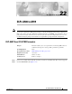
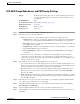
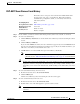
Chapter 22 DLPs A500 to A599 DLP- A507 View OC-N PM Parameters Figure 22-1 Viewing OC-N Card Performance Monitoring Information Card View Performance tab 96974 Directions radio buttons Intervals radio buttons Signal-type port dropdown list Sub-signal STS dropdown list Refresh Auto-refresh Baseline Clear Help button drop-down list button button button Step 3 In the Port drop-down list, click the port you want to monitor. Step 4 Click Refresh.
Chapter 22 DLPs A500 to A599 DLP- A509 Provision CE-1000-4 Ethernet Ports DLP-A509 Provision CE-1000-4 Ethernet Ports Purpose This task provisions CE-1000-4 Ethernet ports to carry traffic.
Chapter 22 DLPs A500 to A599 DLP- A510 Provision a DS-3 Circuit Source and Destination DLP-A510 Provision a DS-3 Circuit Source and Destination Purpose This task provisions an electrical circuit source and destination for a DS-3 circuit.
Chapter 22 DLPs A500 to A599 DLP- A512 Change Node Access and PM Clearing Privilege DLP-A512 Change Node Access and PM Clearing Privilege Purpose This task provisions the physical access points and shell programs used to connect to the ONS 15454 and sets the user security level that can clear node PM data.
Chapter 22 DLPs A500 to A599 DLP- A513 Provision CE-100T-8 Ethernet Ports In the TCC CORBA (IIOP/SSLIOP) Listener Port area, choose a listener port option: • Default - TCC Fixed—Uses Port 57790 to connect to ONS 15454s on the same side of the firewall or if no firewall is used (default). This option can be used for access through a firewall if Port 57790 is open. • Standard Constant—Uses Port 683 (IIOP) or Port 684 (SSLIOP), the Common Object Request Broker Architecture (CORBA) default port number.
Chapter 22 DLPs A500 to A599 DLP- A513 Provision CE-100T-8 Ethernet Ports • Enable Flow Control—Click this check box to enable flow control on the port (default). If you do not want to enable flow control, uncheck the box. The CE-100T-8 attempts to negotiate symmetrical flow control with the attached device. • 802.1Q VLAN CoS—For a class-of-service (CoS)-tagged frame, the CE-100T-8 can map the eight priorities specified in CoS for either priority or best effort treatment.
Chapter 22 DLPs A500 to A599 DLP- A514 Provision CE-100T-8 and CE-1000-4 POS Ports DLP-A514 Provision CE-100T-8 and CE-1000-4 POS Ports Purpose This task provisions CE-100T-8 or CE-1000-4 POS ports to carry traffic.
Chapter 22 DLPs A500 to A599 DLP- A517 View Alarm or Event History DLP-A517 View Alarm or Event History Purpose This task is used to view past cleared and uncleared ONS 15454 alarm messages at the card, node, or network level. This task is useful for troubleshooting configuration, traffic, or connectivity issues that are indicated by alarms.
Chapter 22 DLPs A500 to A599 DLP- A518 Create a New or Cloned Alarm Severity Profile c. Click the History > Session tab to view the alarm messages raised during the current session. d. Click the History > Card tab to retrieve all available alarm messages for the card and click Retrieve. If you check the Alarms check box, the node’s alarm history appears. If you check the Events check box, the node’s Not Alarmed and transient event history appears.
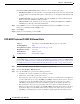
Chapter 22 DLPs A500 to A599 DLP- A518 Create a New or Cloned Alarm Severity Profile Figure 22-2 Node View Alarm Profile Editor Step 3 To access the profile editor from a card view, click the Provisioning > Alarm Profiles > Alarm Profile Editor tabs. Step 4 If you want to create a new profile based upon the default profile in use, click New. Then go to Step 10.
Chapter 22 DLPs A500 to A599 DLP- A518 Create a New or Cloned Alarm Severity Profile Step 9 Click Clone in the shortcut menu. To see the full list of profiles, including those available for loading or cloning, click Available. You must load a profile before you can clone it. Tip Step 10 In the New Profile or Clone Profile dialog box, enter a name in the New Profile Name field. Profile names must be unique.
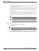
Chapter 22 DLPs A500 to A599 DLP- A518 Create a New or Cloned Alarm Severity Profile Figure 22-3 a. b. Step 16 Step 17 Store Profiles Dialog Box Choose the nodes where you want to save the profile: • If you want to save the profile to only one node, click the node in the Node Names list. • If you want to save the profile to all nodes, click Select All. • If you do not want to save the profile to any nodes, click Select None.
Chapter 22 DLPs A500 to A599 DLP- A519 Apply Alarm Profiles to Ports DLP-A519 Apply Alarm Profiles to Ports Purpose This task applies a custom or default alarm severity profile to a port or ports.
Chapter 22 DLPs A500 to A599 DLP- A520 Delete Alarm Severity Profiles Go to Step 3 to apply profiles to a port. Go to Step 4 to apply profiles to all ports on a card. Step 3 Step 4 To apply profiles on a port basis: a. In card view, click the port row in the Profile column. b. Choose the new profile from the drop-down list. c. Click Apply. To apply profiles to all ports on a card: a. In card view, click the Force all ports to profile drop-down arrow at the bottom of the window. b.
Chapter 22 DLPs A500 to A599 DLP- A520 Delete Alarm Severity Profiles Figure 22-5 Step 6 Select Node/Profile Combination For Delete Dialog Box Note You cannot delete the Inherited or Default alarm profiles. Note A previously created alarm profile cannot be deleted unless it has been stored on the node. If the profile is visible on the Alarm Profiles tab but is not listed in the Select Node/Profile Combinations to Delete dialog box, continue with Step 9.
Chapter 22 DLPs A500 to A599 DLP- A521 Modify Alarm, Condition, and History Filtering Parameters Note Step 10 The Default and Inherited special profiles cannot be deleted and do not appear in the Select Node/Profile Combination for Delete Window. Return to your originating procedure (NTP). DLP-A521 Modify Alarm, Condition, and History Filtering Parameters Purpose This task changes alarm and condition reporting in all network nodes.
Chapter 22 DLPs A500 to A599 DLP- A521 Modify Alarm, Condition, and History Filtering Parameters Step 3 In the Show Severity area, click the check boxes for the severities [Critical (CR), Major (MJ), Minor (MN), or Not-Alarmed (NA)] you want to be reported at the network level. Leave severity check boxes deselected (unchecked) to prevent those severities from appearing. When alarm filtering is disabled, all alarms show.
Chapter 22 DLPs A500 to A599 DLP- A522 Suppress Alarm Reporting DLP-A522 Suppress Alarm Reporting Purpose This task suppresses the reporting of ONS 15454 alarms at the node, card, or port level.
Chapter 22 DLPs A500 to A599 DLP- A523 Discontinue Alarm Suppression Step 7 Click Apply. Alarms that apply directly to this port will change appearance as described in Step 2. (However, alarms raised on the entire card will remain raised.) A raised AS-CMD alarm that shows the port as its object will appear in either alarm window. For example, if you suppressed alarms for Port 1 on the Slot 16 OC-48 card, the alarm object will show “FAC-16-1.” Step 8 Return to your originating procedure (NTP).
Chapter 22 DLPs A500 to A599 DLP- A524 Download an Alarm Severity Profile Suppressed alarms will reappear in the Alarms window. (They might have previously been cleared from the window using the Synchronize button.) The AS-CMD alarm with the port object (for example, FAC-16-1) will be cleared in all views. Step 6 Return to your originating procedure (NTP).
Chapter 22 DLPs A500 to A599 DLP- A526 Change Line and Threshold Settings for the DS3i-N-12 Cards Step 8 Right-click anywhere in the downloaded profile column to view the profile editing shortcut menu. Step 9 Click Store. Step 10 In the Store Profile(s) dialog box, click To Node(s). a. Choose the nodes where you want to save the profile: – If you want to save the profile to only one node, click the node in the Node Names list. – If you want to save the profile to all nodes, click Select All.
Chapter 22 DLPs A500 to A599 DLP- A526 Change Line and Threshold Settings for the DS3i-N-12 Cards For definitions of the line settings, see Table 22-1. For definitions of the line threshold settings, see Table 22-2 on page 22-25. For definitions of the electrical path threshold settings, see Table 22-3 on page 22-25. For definitions of the SONET threshold settings, see Table 22-4 on page 22-25. Table 22-1 describes the values on the Provisioning > Line tabs for the DS3i-N-12 cards.
Chapter 22 DLPs A500 to A599 DLP- A526 Change Line and Threshold Settings for the DS3i-N-12 Cards Table 22-1 Line Options for the DS3i-N-12 Cards (continued) Parameter Description Admin State Sets the port administrative service state unless network conditions prevent the change. Service State AINS Soak (Display only) Identifies the autonomously generated state that gives the overall condition of the port.
Chapter 22 DLPs A500 to A599 DLP- A526 Change Line and Threshold Settings for the DS3i-N-12 Cards Table 22-2 Line Threshold Options for the DS3i-N-12 Cards Parameter Description Port (Display only) Port number; 1 to 12 CV Coding violations.
Chapter 22 DLPs A500 to A599 DLP- A527 Change the OC-N Card ALS Maintenance Settings Table 22-4 Parameter Description ES Errored seconds FC Failure count SES Severely errored seconds UAS Unavailable seconds 15 Min radio button Clicking this radio button and then clicking Refresh will cause the threshold values on this tab to display for 15-minute intervals.
Chapter 22 DLPs A500 to A599 DLP- A527 Change the OC-N Card ALS Maintenance Settings Table 22-5 OC-N Maintenance Settings Parameter Description Options Port number (Display only) Port number — ALS Mode From the drop-down list, choose one Automatic laser shutdown mode. ALS provides the ability to shut down the TX of the following: laser when the RX detects a loss of signal • Disable—Deactivates ALS. (LOS). • Auto Restart—(Default) ALS is active.
Chapter 22 DLPs A500 to A599 DLP- A528 Change the Default Network View Background Map DLP-A528 Change the Default Network View Background Map Purpose This task changes the default map of the CTC network view. Tools/Equipment None Prerequisite procedures DLP-A60 Log into CTC, page 17-69 Note Required/As needed As needed Onsite/Remote Onsite or remote Security Level Superuser If you modify the background image, the change is stored in your CTC user profile on the computer.
Chapter 22 DLPs A500 to A599 DLP- A530 Install the Tie-Down Bar Step 1 Double-click the Ethernet card where you want to delete the RMON alarm thresholds. Step 2 In card view, click the Provisioning > Ether Ports > RMON Thresholds tabs. Note For the CE-Series, click the Provisioning > Ether Ports > RMON Thresholds tabs or Provisioning > POS Ports > RMON Thresholds tabs. Step 3 Click the RMON alarm threshold you want to delete. Step 4 Click Delete. The Delete Threshold dialog box appears.
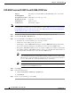
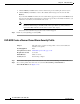
Chapter 22 DLPs A500 to A599 DLP- A531 Print CTC Data Figure 22-8 Tie-Down Bar 105012 Tie-down bar Step 2 Install the four screws into the rack. Step 3 Return to your originating procedure (NTP). DLP-A531 Print CTC Data Step 1 Purpose This task prints CTC card, node, or network data in graphical or tabular format on a Windows-provisioned printer.
Chapter 22 DLPs A500 to A599 DLP- A531 Print CTC Data • Tabbed View—Prints the lower half of the CTC window containing tabs and data. The printout includes the selected tab (on top) and the data shown in the tab window. For example, if you print the History window Tabbed View, you print only history items appearing in the window. This option is available for all windows. • Table Contents—Prints CTC data in table format without graphical representations of shelves, cards, or tabs.
Chapter 22 DLPs A500 to A599 DLP- A532 Export CTC Data Step 6 Repeat this task for each window that you want to print. Step 7 Return to your originating procedure (NTP). DLP-A532 Export CTC Data Purpose This task exports CTC table data as delineated text to view or edit the data in text editor, word processor, spreadsheet, database management, or web browser applications. You can also export data from the Edit Circuits window.
Chapter 22 DLPs A500 to A599 DLP- A532 Export CTC Data Step 5 If you want to open a file in a text editor or word processor application, procedures vary. Typically, you can use the File > Open command to view the CTC data, or you can double-click the file name and choose an application such as Notepad. Text editor and word processor applications format the data exactly as it is exported, including comma or tab separators. All applications that open the data files allow you to format the data.
Chapter 22 DLPs A500 to A599 DLP- A533 Create Ethernet RMON Alarm Thresholds DLP-A533 Create Ethernet RMON Alarm Thresholds Purpose This procedure sets up remote monitoring (RMON) to allow network management systems to monitor Ethernet ports.
Chapter 22 DLPs A500 to A599 DLP- A533 Create Ethernet RMON Alarm Thresholds Table 22-6 Ethernet Threshold Variables (MIBs) Variable Definition iflnOctets Total number of octets received on the interface, including framing octets iflnUcastPkts Total number of unicast packets delivered to an appropriate protocol ifInMulticastPkts (G-Series, CE-Series, and ML-Series only) Number of multicast frames received error free ifInBroadcastPkts (G-Series, CE-Series, and ML-Series only) The number of packe
Chapter 22 DLPs A500 to A599 DLP- A533 Create Ethernet RMON Alarm Thresholds Table 22-6 Ethernet Threshold Variables (MIBs) (continued) Variable Definition dot3StatsExcessiveCollisions (Not supported by E-Series or G-Series) Number of frames where transmissions failed because of excessive collisions dot3StatsCarrierSenseErrors (G-Series only) The number of transmission errors on a particular interface that are not otherwise counted dot3StatsSQETestErrors (G-Series only) A count of times that the
Chapter 22 DLPs A500 to A599 DLP- A533 Create Ethernet RMON Alarm Thresholds Table 22-6 Ethernet Threshold Variables (MIBs) (continued) Variable Definition etherStatsCollisionFrames An estimate of the total number of collisions on this Ethernet segment. The value returned will depend on the location of the RMON probe. Section 8.2.1.3 (10Base5) and Section 10.3.1.3 (10Base2) of the IEEE 802.
Chapter 22 DLPs A500 to A599 DLP- A533 Create Ethernet RMON Alarm Thresholds Table 22-6 Ethernet Threshold Variables (MIBs) (continued) Variable Definition etherStatsPkts512to1023Octets Total number of packets received (including error packets) that were 512 to 1023 octets in length etherStatsPkts1024to1518Octets Total number of packets received (including error packets) that were 1024 to 1518 octets in length etherStatsJabbers Total number of packets longer than 1518 octets that were not an int
Chapter 22 DLPs A500 to A599 DLP- A533 Create Ethernet RMON Alarm Thresholds Table 22-7 POS Threshold Variables (MIBs) (continued) Variable Definition gfpStatsRxTypeInvalid Receive frames with invalid type (PTI, EXI, UPI) gfpStatsRxCRCErrors Receive data frames with Payload cyclic redundancy check (CRC) errors gfpStatsRxCIDInvalid Receive frames with Invalid CID gfpStatsCSFRaised Number of receive (Rx) client management frames with Client Signal Fail indication.
Chapter 22 DLPs A500 to A599 DLP- A534 Provision OSI Routing Mode DLP-A534 Provision OSI Routing Mode Purpose This task provisions the Open System Interconnection (OSI) routing mode. Complete this task when the ONS 15454 is connected to networks with third party network elements (NEs) that use the OSI protocol stack for data communications network (DCN) communication.
Chapter 22 DLPs A500 to A599 DLP- A535 Provision or Modify TARP Operating Parameters • Intermediate System Level 1/Level 2—The ONS 15454 performs IS functions. It communicates with IS and ES nodes that reside within its OSI area. It also communicates with IS L1/L2 nodes that reside in other OSI areas. Before choosing this option, verify the following: – The node is connected to another IS Level 1/Level 2 node that resides in a different OSI area.
Chapter 22 DLPs A500 to A599 DLP- A535 Provision or Modify TARP Operating Parameters • TARP PDUs Origination—If checked (default), the node performs all TARP origination functions including: – TID to Network Service Access Point (NSAP) resolution requests (originate TARP Type 1 and Type 2 PDUs) – NSAP to TID requests (originate Type 5 PDUs) – TARP address changes (originate Type 4 PDUs) Note • TARP Data Cache—If checked (default), the node maintains a TARP data cache (TDC).
Chapter 22 DLPs A500 to A599 DLP- A536 Add a Static TID to NSAP Entry to the TARP Data Cache • T2—Sets the amount of time to wait for a response to a Type 2 PDU. TARP Type 2 PDUs seek a specific NE TID value within OSI Level 1 and Level 2 areas. The default is 25 seconds. The range is 0 to 3600 seconds. • T3—Sets the amount of time to wait for an address resolution request. The default is 40 seconds. The range is 0 to 3600 seconds. • T4—Sets the amount of time to wait for an error recovery.
Chapter 22 DLPs A500 to A599 DLP- A537 Remove a Static TID to NSAP Entry from the TARP Data Cache DLP-A537 Remove a Static TID to NSAP Entry from the TARP Data Cache Purpose This task removes a static TID to NSAP entry from the TDC. Tools/Equipment None Prerequisite procedures DLP-A60 Log into CTC, page 17-69 Required/As needed As needed Onsite/Remote Onsite or remote Security Level Provisioner or higher Step 1 In node view, click the Provisioning > OSI > TARP > Static TDC tabs.
Chapter 22 DLPs A500 to A599 DLP- A539 Provision OSI Routers Step 4 Click OK to close the Masked NSAP Entry dialog box, if used, and then click OK to close the Add Static Entry dialog box. Step 5 Return to your originating procedure (NTP). DLP-A539 Provision OSI Routers Purpose This task enables an OSI router and edits its primary manual area address.
Chapter 22 DLPs A500 to A599 DLP- A540 Provision Additional Manual Area Addresses DLP-A540 Provision Additional Manual Area Addresses Purpose This task provisions the OSI manual area addresses. One primary and two additional manual areas can be created for each virtual router.
Chapter 22 DLPs A500 to A599 DLP- A541 Enable the OSI Subnet on the LAN Interface Note The OSI subnetwork point of attachment cannot be enabled for the LAN interface if the OSI routing mode is set to ES (end system). Note If Secure Mode is on, the OSI Subnet is enabled on the backplane LAN port, not the front TCC2P port. Step 1 In node view, click the Provisioning > OSI > Routers > Subnet tabs. Step 2 Click Enable LAN Subnet.
Chapter 22 DLPs A500 to A599 DLP- A542 Create an IP-Over-CLNS Tunnel DLP-A542 Create an IP-Over-CLNS Tunnel Purpose This task creates an IP-over-CLNS tunnel to allow ONS 15454s to communicate across equipment and networks that use the OSI protocol stack. Tools/Equipment None Prerequisite Procedures DLP-A60 Log into CTC, page 17-69 Caution Required/As Needed As needed Onsite/Remote Onsite or remote Security Level Provisioning or higher IP-over-CLNS tunnels require two end points.
Chapter 22 DLPs A500 to A599 DLP- A543 Remove a TARP Manual Adjacency Table Entry Step 5 Provision the other tunnel end point using the documentation. Step 6 Return to your originating procedure (NTP). DLP-A543 Remove a TARP Manual Adjacency Table Entry Purpose This task removes an entry from the TARP manual adjacency table.
Chapter 22 DLPs A500 to A599 DLP- A544 Change the OSI Routing Mode Caution Step 1 LSP buffer sizes cannot be greater than the LAP-D MTU size within the OSI area. Verify the following: • All L1/L2 virtual routers on the NE must reside in the same area. This means that all neighboring virtual routers must have at least one common area address. • For OSI L1/L2 to ES routing mode changes, only one L1/L2 virtual router and no more than one subnet can be configured.
Chapter 22 DLPs A500 to A599 DLP- A545 Edit the OSI Router Configuration DLP-A545 Edit the OSI Router Configuration Purpose This task allows you to edit the OSI router configuration, including enabling and disabling OSI routers, editing the primary area address, and creating or editing additional area addresses.
Chapter 22 DLPs A500 to A599 DLP- A547 Edit an IP-Over-CLNS Tunnel Step 2 Choose the subnet you want to edit, then click Edit. Step 3 In the Edit Subnet dialog box, edit the following fields: • ESH—The End System Hello PDU propagation frequency. An end system NE transmits ESHs to inform other ESs and ISs about the NSAPs it serves. The default is 10 seconds. The range is 10 to 1000 seconds. • ISH—The Intermediate System Hello PDU propagation frequency.
Chapter 22 DLPs A500 to A599 DLP- A548 Delete an IP-Over-CLNS Tunnel The Cisco proprietary tunnel is slightly more efficient than the GRE tunnel because it does not add the GRE header to each IP packet. The two tunnel types are not compatible. Most Cisco routers support the Cisco IP tunnel, while only a few support both GRE and Cisco IP tunnels. You generally should create Cisco IP tunnels if you are tunneling between two Cisco routers or between a Cisco router and an ONS node.
Chapter 22 DLPs A500 to A599 DLP- A549 View IS-IS Routing Information Base DLP-A549 View IS-IS Routing Information Base Purpose This task allows you to view the Intermediate System to Intermediate System (IS-IS) protocol routing information base (RIB). IS-IS is an OSI routing protocol that floods the network with information about NEs on the network. Each NE uses the information to build a complete and consistent picture of a network topology.
Chapter 22 DLPs A500 to A599 DLP- A550 View ES-IS Routing Information Base DLP-A550 View ES-IS Routing Information Base Purpose This task allows you to view the End System to Intermediate System (ES-IS) protocol routing information base (RIB). ES-IS is an OSI protocol that defines how end systems (hosts) and intermediate systems (routers) learn about each other. For ESs, the ES-IS RIB shows the network view from the perspective of the ES node.
Chapter 22 DLPs A500 to A599 DLP- A552 Adjust the Java Virtual Memory Heap Size Step 2 View the following TARP data cache information: • TID—The target identifier of the originating NE. For ONS 15454s, the TID is the name entered in the Node Name/TID field on the Provisioning > General tab. • NSAP/NET—The Network Service Access Point or Network Element Title of the originating NE.
Chapter 22 DLPs A500 to A599 DLP- A553 Upgrade DS1 or DS3-12 Cards in a 1:N or 1:1 Configuration to High-Density Electrical Cards Step 6 Type “CTC_HEAP” in the Variable Name field. Step 7 Type “512” in the Variable Value field. Step 8 Click OK. Step 9 Reboot your PC. Step 10 Return to your originating procedure (NTP).
Chapter 22 DLPs A500 to A599 DLP- A553 Upgrade DS1 or DS3-12 Cards in a 1:N or 1:1 Configuration to High-Density Electrical Cards • For 1:N protection groups where N = 2: On the A side, the protect card cannot be upgraded if any electrical cards are installed or preprovisioned in Slots 4, 5, or 6 (or Slots 12, 13, or 14 on the B side).
Chapter 22 DLPs A500 to A599 DLP- A553 Upgrade DS1 or DS3-12 Cards in a 1:N or 1:1 Configuration to High-Density Electrical Cards Step 11 Step 12 Step 13 b. Click the Maintenance > Protection tabs. c. Double-click the protection group that contains the working card. d. Click the low-density card slot. e. Click Switch and Yes in the Confirmation dialog box. Physically remove the low-density card you switched traffic away from in Step 10: a. Open the card ejectors. a.
Chapter 22 DLPs A500 to A599 DLP- A553 Upgrade DS3XM-6 Cards in a 1:1 Configuration to High-Density DS3XM-12 Electrical Cards Step 16 Return to your originating procedure (NTP). DLP-A553 Upgrade DS3XM-6 Cards in a 1:1 Configuration to High-Density DS3XM-12 Electrical Cards Purpose This task upgrades low-density electrical cards in a 1:1 protection scheme to high-density electrical cards (DS3XM-12 cards).
Chapter 22 DLPs A500 to A599 DLP- A553 Upgrade DS3XM-6 Cards in a 1:1 Configuration to High-Density DS3XM-12 Electrical Cards The following limitations apply to upgrading a working card after you have upgraded the protect card: • A working card on the A cannot be upgraded if an DS1 card is installed or preprovisioned in A side. • A working card on the B side cannot be upgraded if an DS1 card is installed or preprovisioned in B side. Step 4 In node view, double-click the current protect card.
Chapter 22 DLPs A500 to A599 DLP- A553 Upgrade DS3XM-6 Cards in a 1:1 Configuration to High-Density DS3XM-12 Electrical Cards Step 13 b. Choose the new high-density card type from the Change to drop-down list. c. Click OK. Insert the new high-density electrical card into the slot where you removed the low-density card. Be sure to remove the plastic protective covers on rear of the card before installing the card: a. Open the ejectors on the card. b.
Chapter 22 DLPs A500 to A599 DLP- A554 Upgrade EC-1 Cards in a 1:1 Configuration to DS3/EC1-48 Cards DLP-A554 Upgrade EC-1 Cards in a 1:1 Configuration to DS3/EC1-48 Cards Purpose This task upgrades low-density electrical cards in a 1:N protection scheme (where N = 1 or 2) to high-density electrical cards (DS3/EC1-48, DS1/E1-56, and DS3XM-12 cards). Low-density cards are defined as DS-1 and DS3-12.
Chapter 22 DLPs A500 to A599 DLP- A554 Upgrade EC-1 Cards in a 1:1 Configuration to DS3/EC1-48 Cards Slot 1 contains the protect card if you are working on the A side of the shelf, and Slot 17 contains the protect card if you are working on the B side of the shelf. Step 5 Step 6 Step 7 Make sure the current protect card is not active: a. In card view, click the Maintenance > Protection tabs. b. Select the protection group where the protect card resides.
Chapter 22 DLPs A500 to A599 DLP- A554 Upgrade EC-1 Cards in a 1:1 Configuration to DS3/EC1-48 Cards Step 12 Step 13 Change the low-density card to the high-density card in CTC: a. Right-click Slot 1/Slot 17 and choose Change Card from the drop-down list. b. Choose the new card type from the Change to drop-down list. c. Click OK. Insert the new high-density electrical card into Slot 1/Slot 17. Be sure to remove the plastic protective covers on rear of the card before installing the card: a.
Chapter 22 DLPs A500 to A599 DLP- A554 Upgrade EC-1 Cards in a 1:1 Configuration to DS3/EC1-48 Cards Cisco ONS 15454 Procedure Guide, R7.