
Performance Routing Installation Guide
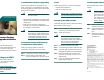

0000 Series Router
BR10012 Router
p and bottom ejector levers
sly to firmly seat the module
lane.
top and bottom captive
cables to the PRE3 and
PRE3 to the console.
e router.
image from the TFTP server.
32682
5
6
7
8
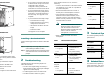
PERFORMANCE ROUTING ENGINE
L
LE
E
T
Y
CISCO
10000
CARRIER
ALARM
LOOP
FAIL
6XCT3–DS0
0
5
4
3
2
1
CISCO
10000
CARRIER
ALARM
LOOP
FAIL
6XCT3–DS0
0
5
4
3
2
1
CISCO
10000
CARRIER
ALARM
LOOP
FAIL
6XCT3–DS0
0
5
4
3
2
1
CISCO
10000
CARRIER
TX
RX
FAIL
OC–12/STM–4 POS SM–IR
122201
POWER
MISWIRE
FAULT
• If you need to access the TFTP server
to obtain the full image or the saved
configuration files, enter the
configuration dialog and enter the
information to access the TFTP server.
• If you booted the full image, restore
the startup and running configuration
information, and set the variable for
the new image. The upgrade is now
complete.
• If you booted from the helper image:
–
Download the full image.
–
Restore the startup and running
configuration information.
–
Set the boot variable to the new
image.
–
Reload the router.
The upgrade is now complete.
Installing a Redundant PRE3
Use the following procedure to install a redundant
PRE3.
Step 1 Repeat Step 1 through Step 8 for slot B
(see Installing the PRE3 Module).
Step 2 Settheconfigurationtobootthefullimage
and reload from the console ROMMON
prompt.
2 Troubleshooting
The PRE3 displays the following sequence of
events when booted:
• The FAIL LED lights briefly, followed by a
flashing STATUS LED, and progress messages
appear on the PRE3 display.
• IOS RUN appears after a successful boot.
• The STATUS LED remains on (green).
If this sequence does not occur, check the
following:
• Check to see if the LEDs on the other modules
are operating. If not, check for a problem in
the power subsystem.
• Remove the PRE3 and check for bent or
broken pins on the backplane connectors.
• Verify the status of the PRE3s internal
Ethernet interface (ethernet 0/0/0). If this
interface is down it could indicate that the
PRE3 is not fully seated in the slot, or that a
hardware failure occurred.
Note Do not confuse the PRE3 internal
Ethernet interface (ethernet 0/0/0)
with the module’s external Fast
Ethernet interface (fastethernet 0/0/0)
which is used for network
management or remote access.
• Refer to Table 1 for LED and switch
descriptions.
Table 1 LED and Switch Descriptions
LED/Switch Description
ACTIVITY
• On (green)
• Off
• Packets are being
transmitted and
received.
• No packet activity.
LINK
• On (green)
• Off
• Carrier detected and
passing traffic.
• No carrier detected
and not passing
traffic.
CRITICAL
MAJOR
MINOR
• Off
• On (yellow)
• No alarm.
• Alarm condition is
present.
3 Technical Sp
e
The following table provides
t
specifications.
4 Related Docu
The release notes, regulatory
safety information, and user
g
products are available online
STATUS
• On (green)
• Off
• P
R
•
N
o
r
r
e
FAIL
• Off
• On (yellow)
• P
R
p
r
• P
R
c
a
f
a
ACO
1
switch Disab
l
alarm
1. Alarm cutoff
Description
Par
t
Spe
PRE3
PRE3 spare
ES
R
ES
R
Weight 9 lb
Powerconsumptionper
PRE3 module
145
no
m
200
ma
x
LED/Switch Descr
i