4119-7704-02 CF 911 P Operator’s Manual
i Using the Printer Properly To ensure the optimum performance of the printer, follow the precautions listed below. • • • • • • • • • • • • • • • • • • • • • Never place a heavy object on the printer. Never subject the printer to shocks. Never open any doors or turn the printer off while the printer is making printings. Never bring any magnetized object near the printer. Never use flammable sprays, liquids or gases near the printer. Never modify the printer, as a fire or electrical shock could result.
ii Using the Printer Properly • • • • • Always use the correct power voltage, as improper voltage can cause a fire or electrical shock. Never use a multiple outlet adapter, as a fire or electrical shock can result. Should the power cord become damaged, immediately turn the printer off, unplug the power cord and call your technical representative. A damaged cord can result in a fire or cause an electric shock.
iii Safety Information SAFETY INFORMATION This color printer is a digital printer which operates by means of a laser. There is no possibility of danger from the laser, provided the printer is operated according to the instructions in this manual. Since radiation emitted by the laser is completely confined within protective housing, the laser beam cannot escape from the machine during any phase of user operation. This machine is certified as a Class 1 laser product.
iv Safety Information For European Users: WARNING Use of controls, adjustments or performance of procedures other than those specified in this manual may result in hazardous radiation exposure. This is a semiconductor laser. The maximum power of the laser diode is 26.79µW and the wavelength is 780nm. For Denmark Users: ADVARSEL Usynlig laserstråling ved åbning, når sikkerhedsafbrydere er ude af funktion. Undgå udsættelse for stråling. Klasse 1 laser produkt der opfylder IEC825 sikkerheds kravene.
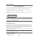
v Safety Information Laser Safety Labels [Label on printer surface] A laser safety label is attached to the outside of the printer as shown below. C4119O009AA Manufacturer’s Name Plate The Manufacturer’s Name Plate is affixed at the position illustrated above. Please write down the Model Name and Serial No. of your printer here, if necessary. Model: Serial No.
vi Regulatry Information WARNING This equipment has been tested and found to comply with the limits for a Class A digital device, pursuant to Part 15 of the FCC Rules. These limits are designed to provide reasonable protection against harmful interference when the equipment is operated in a commercial environment.
vii Regulatry Information Thank you for choosing Minolta. This operator’s manual explains how to operate the color printer and replenish its supplies. It also gives some troubleshooting tips as well as general precautions to be observed when operating the color printer. To ensure the best performance and effective use of your color printer, read this manual carefully until you familiarize yourself thoroughly with its operation and features.
viii Technical Support Thank you for choosing Minolta quality. For over 30 years Minolta has been a leader on the forefront of office equipment technology and service. Our desire has always been to bring you highly reliable products. We pledge to continue to provide you, our customer, with our state of the art equipment, as well as full customer service for all our products. We look forward to a long healthy relationship with you and our company.
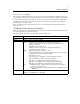
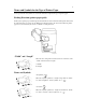
ix Terms and Symbols for the Type of Printer Paper A few special terms and symbols are used in this manual to designate the types of printer paper. Feeding Direction (printer paper path) In this system, printer paper is taken up from the left-hand side of the unit and fed through the unit toward the right-hand side, face-down onto the Exit Tray. In the figure below, the direction in which the printer paper is fed, as indicated by the arrow, is called the “feeding direction”.
Contents x Contents Organization Chapters 1 through 3 contain the basic information for making prints. Be sure to read these chapters before attempting to use your printer. Using the Printer Properly ................................................................................ i Safety Information .......................................................................................... iii Regulatory Information.....................................................................................
Chapter 4 Setup Menu Settings .............................................................................4-1 1. Setup Menu Summary ................................................................................. 4-2 Possible Setting Items in the Setup Menu.................................................... 4-2 Setup Menu Hierarchy ................................................................................. 4-3 Setup Menu Keys ........................................................................
Contents xii
Safety Notes Chapter 1 1-1 Chapter 1 Safety Notes
1-2 1. Installing the Printer To ensure optimal safety and prevent possible malfunctions of the unit, install the printer in a location which meets the following requirements. ◆ A place away from a curtain or the like that may ◆ catch fire and burn easily. ◆ ◆ An area where there is no possibility of being ◆ splashed with water or other types of liquid. ◆ ◆ An area free from direct sunlight. ◆ A place out of the direct air stream of an air ◆ conditioner, heater, or ventilator. ◆ A well-ventilated place.
1-3 2. Precautions for Use Operating Environment Temperature Humidity : 10°C to 30°C (50°F to 86°F) with a fluctuation of 10°C (50°F) per hour. : 25% to 85% with a fluctuation of 20% per hour. Chapter 1 The operating environmental requirements of the printer are as follows. To ensure the optimum performance of the unit, follow the precautions listed below. ◆ ◆ ◆ ◆ ◆ ◆ ◆ NEVER place a heavy object on the unit or subject the unit to any shock.
1-4 2. Precautions for Use Safety Notes Chapter 1 Storage of Prints • If prints are to be kept for a long time, keep them in a place which is not exposed to light to prevent fading. • If an adhesive containing solvent (e.g., spray glue) is used to past printings, the toner on the prints can melt. • The color prints have a toner layer thicker than the normal black-and-white prints. When a color print is folded, therefore, the toner can be broken at the fold.
Chapter 2 Getting to Know Your Printer Getting to Know Your Printer Chapter 2 2-1
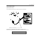
2-2 1. System Overview Getting to Know Your Printer Chapter 2 System Overview 1144O003AB 1139O0020A 1154O028AA Sorter S-105/Staple Sorter ST-103
2-3 2. Printer Parts and Accessories C4119O004AA Exit Tray: Holds the prints ejected from the unit. Manual Bypass Tray: Use for manual feeding of printer paper into the unit. Upper/Lower Tray: Holds up to 500 sheets of paper. ☞ p. 6-2 Middle Tray (Universal): Holds up to 250 sheets of paper. ☞ p. 6-2 Front Door: Open to clear a paper misfeed or add toner. ☞ pp. 6-4, 6-9 Operation Panel: Use to verify the printer condition and perform the menu settings. See Operation Panel Keys and Touch Panel.
2-4 2. Printer Parts and Accessories Getting to Know Your Printer Chapter 2 Inside the Unit C4119O005AA Toner Hopper Lid: M1 ~ M9 : Open when adding toner. ☞ p. 6-4 Operate these parts to clear misfed sheets of paper. ☞ p. 6-8 Connector Layout IEEE1284: This is connected to the printer port of the computer by a parallel interface cable. Ethernet (10/100 Base-T): This is connected to the computer through the network and corresponds to 10/100 Base-T.
2-5 2. Printer Parts and Accessories Getting to Know Your Printer Chapter 2 Options C4119O006AA Sorter / Staple Sorter Stapler Door: Open to replace the Staple Cartridge. ☞ p. 6-6 Sort Bins: Holds sorted or grouped prints. Large Capacity Cassette Cassette Release Lever: Use to release the cassette from the unit when it is necessary to clear a misfeed. Paper Plate Descent Key: Press to lower the paper plate. Cassette Door: Open to add paper or clear a misfed sheet of paper.
2-6 3. Operation Panel Operation Panel Names and Functions 1234567890123456 ABCDEFGHIJKLMNOP Getting to Know Your Printer Chapter 2 O C C4119O023AA Message LED ON: A communication error has occurred between the Fiery X2e and the printer. Blinking: An error has occurred that prevents printing. OFF: There is no error. Cancel key When the printer is in printer mode, switches from the Functions screen to the Status screens. If pressed before paper feeding begins, cancels the current printing job.
2-7 4. Computer Connection Parallel Connection Chapter 2 Use a parallel interface cable when connecting this unit to the printer port of a computer. Network Connection Use a network cable of 10Base-T or 100Base-T when connecting this unit to a computer by a network.
2-8 5. Turning ON and OFF Turning ON and OFF • Turning the printer ON Press the Power Switch to the Chapter 2 • Turning the printer OFF Press the Power Switch to the (ON) position. (OFF) position. C4119O010AA Getting to Know Your Printer When the unit is turned ON The operation panel changes as follows when the power is turned ON. (1) The printer self-test operation is performed automatically. START SELF_TEST (2) It then enters the setup stand-by mode. Press any key (i.e.
2-9 5. Turning ON and OFF Continuous Printing Precautions Getting to Know Your Printer * These figures vary according to the selected print size and other setting conditions. Chapter 2 The printing operation stops for the following intervals and the transfer drum cleaning operation is performed for approximately 40 seconds to maintain optimal performance of the color printer. Wait a moment when this condition occurs. Full-color or monochrome printing:..............
Getting to Know Your Printer Chapter 2 2-10
Printing Procedures Printing Procedures Chapter 3 Chapter 3 3-1
3-2 1. Printing Printing Preparations The printer driver for this unit must be installed in advance in the computer to perform the printing operations. Refer to the separate Getting Started manual for a description of the printer driver installation procedures. Performing Printing Printing Procedures Chapter 3 The software application which creates the document performs the printing. Various functions can be set by the print driver at this time. Refer to the separate User Guide.
3-3 2. Function Settings Application Specification The size and color of the document can be set by the software application of the document. Check the functions which can be set in the operation manual of the software application. Printer Driver Specification Special functions of this printer such as the sort and staple operation are set by the functions of the printer driver. The printer driver can be called from any dialog box that is opened when printing is performed.
Printing Procedures Chapter 3 3-4
Setup Menu Settings Setup Menu Settings Chapter 4 Chapter 4 4-1
4-2 1. Setup Menu Summary Possible Setting Items in the Setup Menu The connection port, network settings, print job management and other items in the setup menu set the conditions when printing is performed. The main menu contains the following selections. There are lower-position sub-menus depending on the main menu and the various items that can be set. Refer to the Setup Menu Transition diagram (☞ p. 4-11) for a detailed description of the possible setting items.
4-3 1. Setup Menu Summary Setup Menu Hierarchy The setup menu contains a number of levels of submenus under the main menu that were explained in the chart on the previous page. A submenu is separated into four levels. The lowest levels are [Network Setup], [Protocol Setup], [IPX/SPX Setup] and [Frame Types].
4-4 2. Setup Menu Procedures Starting the Setup Menu. The Setup menu is made available when the printer is started. (1) Turn on the power. (2) Press any key (i.e. the menu key) when the following message is displayed. To update/setup Press any key This message is displayed for approximately 5 seconds. If no operation is performed at this time, the printer ready mode is set. The following service option screen is displayed by pressing any key.
4-5 2. Setup Menu Procedures Operating the Setup Menu The Setup menu is accessed in the following sequence: Menu selection → Set key → Submenu selection → Set key → Select the desired setting menu and change the setting. Refer to the section “Setup Menu Transition Diagram” (☞ p. 4-11) for an illustration of the menu hierarchy and the items that can be set. (1) Use the ▼ and ▲ keys to select the main menu. Setup EXIT ▼ ▲ Setup Server Setup ▼ ▲ Setup Network Setup (Next menu) (2) Press the Set key.
4-6 2. Setup Menu Procedures (4) Press the Set key. Level 2 of the selected submenu (Level 1) is displayed. There may not be a Level 2 depending on the main menu that is selected, and the setting item is displayed instead (☞ p. 4-11). This example indicates the condition when [Protocol Setup] is selected in the first level. Set key Network Setup Protocol Setup Protocol Setup EXIT (5) Use the ▼ and ▲ keys to select the submenu hierarchy (Level 2).
4-7 2. Setup Menu Procedures (8) Press the Set key. The first setting item of the selected submenu (Level 3) is displayed. The menu on Level 4 may be displayed depending on the main menu that is selected (☞ p. 4-11). Select the menu in the same manner. This example describes the condition when the [Ethernet Setup] is selected in the level 3. Set key TCP/IP Setup Ethernet Setup Enable TCP/IP No Useful Tip The [Network Setup] settings are required when the printer is connected to a network.
4-8 3. Server Setup Menu Server Setup Menu Hierarchy The information for the print server and the job processing procedures are set in the Server Setup menu. The setting items are displayed if the main menu is selected instead of the server menu.
4-9 3. Server Setup Menu System Date System Date 00/00/00 Date ▼ Function: This sets the style of the date for the printer time (date information) to Month/Day/ Year. Operation: Use the ▼ and ▲ keys to switch the display of the numeric characters. Use the key to shift the cursor (underlined section). Repeat this operation to set the date. After this operation is performed, press the Set key to display the following item, [System Time].
4-10 3. Server Setup Menu Enable Printed Queue Enable Printed Q Yes Function: The setting determines if the print queue is used. Operation: Use the ▼ and ▲ keys to switch the Yes/No setting. Press the Set key to display the next item [Jobs to Save]. If “No” is set, [Save Change] is displayed if the Set key is pressed. [Save Change] will be displayed if the Cancel key is pressed midway through the process.
4-11 4. Setup Menu Transition Diagram The setup menu configuration is shown in the Menu Map. Before starting the settings, verify the position and structure of the required setting items. Setup Menu Settings Chapter 4 To print out the Menu Map: Press the Menu key. The message “Print Pages” appears, press the Set key. Press the down key and select “Menu Map”. Press the Set key. The Menu Map is printed out.
Setup Menu Settings Chapter 4 4-12
5-1 Chapter 5 Function Menu Settings Chapter 5 Function Menu Settings
5-2 1. Function Menu Summary Function Menu Setting Items A test pattern that verifies the printer conditions can be printed and printing can be suspended (temporary stop) and resumed (start operation again) in the function menu. The main menu contains the following selections. There are lower-position submenus depending on the main menu and various items can be set. Refer to the Function Menu Transition Diagram (☞ p. 5-4) for a detailed description of the possible setting items.
5-3 2. Function Menu Operation Procedures Starting the Function Menu (1) Press the MENU key. The function menu is accessed and the following screen is displayed. Functions Print Page Function Menu Keys The following keys are used to move the among menus. ▲ ▲ ▲ , ▼ keys: , keys: Set key: Cancel key: These keys switch between the menus, items and setting values that are displayed. The operation is performed in the sequence indicated by the vertical arrow marks in the figures.
5-4 3. Function Menu Transition Diagram The function menu configuration is shown in the following diagram. Before starting the settings, verify the position and structure of the required setting items. Main Menu Function Print Pages Sub Menu Set key Print Pages Test Page Setting Items Test Print Setting Items Go to the main menu after printing. Function Menu Settings Chapter 5 ▼ key Print Pages Configuration Go to the main menu after printing.
6-1 Chapter 6 When a Message Appears Chapter 6 When a Message Appears
6-2 1. When the Message “LOAD IN ANY TRAY” is displayed. The message shown on the left is displayed when the Tray currently selected for use runs out of paper. The current print cycle is interrupted and you cannot start a new print cycle. Load the tray with paper by performing the following procedure: Paper Size LOAD A4 IN LOWER TRAY NOTE Only the following type of paper can be loaded in the tray.
6-3 1. When the Message “LOAD IN ANY TRAY” is displayed. Changing the Paper Size for the Middle Tray (Universal Tray) 1 Large Capacity Cassette Grasp the tab of the Edge Guide and slide it to the size of the paper to be loaded. Pressing the plastic part of the Trailing Edge Stop, slide it to the size of the paper to be loaded. 1 Grasping the Door Lock Release Lever, open the Cassette Door.
6-4 2. When the Message “TONER NEAR EMPTY” or “NO TONER” Appears The message shown on the left appears when toner will run out soon. You can still make prints, but the image density will become lighter and lighter. It is recommended that you replenish the toner as soon as possible for this reason. TONER NEAR EMPTY YELLOW Toner Color When toner has run out, the message shown on the left is displayed and you can no longer start a new print cycle.
6-5 2. When the Message “TONER NEAR EMPTY” or “NO TONER” Appears 5 Remove the bottle cap and peel off the seal. 8 After the toner stops falling in (approx. 60 seconds), tap the Bottle a few times to ensure that all the toner falls into the Hopper. 1144L016AA 6 Open the Toner Hopper Lid. 1144L018AA 9 Making sure that the toner has emptied completely, turn the Bottle counterclockwise and lift it out of the Receptacle. Close the Toner Hopper Lid.
6-6 3. When the Message “NO STAPLE” Appears The message shown on the left appears when the staples are running out. NO STAPLE Replace the Staple Cartridge with a new one by following the procedure given below. Replacing the Staple Cartridge 1 While holding the Lock Release Lever, slide the Staple Sorter away from the unit. 2 Open the Stapler Door. NOTE Check that no portion of the staple sheet hangs out of the Cartridge. Break off any portion of the sheet that hangs out of the Cartridge.
6-7 3. When the Message “NO STAPLE” Appears 7 Place a sheet of paper into the 2nd Bin of the Staple Sorter. C4119O014AA NOTES • Replace the Staple Cartridge only after you are prompted to do so by the message. Removing the Staple Cartridge before then will result in stapling trouble. • Immediately after the new Staple Cartridge has been loaded, be sure to test-staple the paper following steps 7 through 9. • DO NOT turn the green gear near the Cartridge inside the Staple Unit.
6-8 4. When “Misfeeding Occurs.” If a paper misfeed occurs during a print cycle, the message shown on the left is displayed and that particular print cycle is stopped in the middle of operation. Clear the misfed sheet of paper according to the procedure given below. Misfeed Location Different procedures are used to clear a misfed sheet of paper depending on the location. First, isolate the location, then clear the misfeed following the procedure applicable to where the misfeed occurred.
6-9 4. When “Misfeeding Occurs.” Misfeed in the unit 1 Open the Left Door L1 . 5 Close the Left Door L1 . L1 L1 1144O548AA 2 Pull out the sheet of paper from the Transport Section. 1144O549AA 6 Open the Front Door. 1144L022AA 3 Raise the Guide Plate M2 , turn Knob M1 and pull out the sheet of paper. C4119O010AA Chapter 6 M1 Turn Lever M4 to the left. Press Guide Plate L2 , turn Knob M5 and pull out the sheet of paper.
6-10 4. When “Misfeeding Occurs.” Grasp the Fusing Unit Lever M7 and open the Fusing Unit. 9 turning Knob M9 , remove the sheet 12 While of paper. If the paper adheres to the Transfer Film, gently disengage the leading edge of the paper and remove it, being careful not to damage the Transfer Film. M7 1144L028AB CAUTION M9 1144L031AA DO NOT touch any parts except the paper as the Fusing Unit and its surrounding areas are extremely hot.
6-11 4. When “Misfeeding Occurs.” Paper Trays 1 Manual Bypass Tray Open the Left Door L1 and pull out the sheet of paper from the Transport Section. 1 Unload the paper stack from the Manual Bypass Tray. Then open the Left Door L1 . L1 1144L022AA 2 Close the Left Door L1 . 3 Slide the Tray out. 1144O548AA 2 Pull out the sheet of paper. Raise the Guide plate M2 , turning knob M1 and pull out the sheet of paper and close the Left Door.
6-12 4. When “Misfeeding Occurs.” Large Capacity Cassette 1 Press the Paper Descent Key. 5 Remove the sheet of paper. 6 Slide the Cassette back against the printer. 1154O036AA 1154O031AA 2 Grasping the Door Lock Release Lever, open the Cassette Door and remove the sheet of paper. 1154O037AA 1154O034AA Close the Cassette Door. 4 Slide the cassette away from the main unit.
6-13 4. When “Misfeeding Occurs.” Duplex Unit 1 Sorter/Staple Sorter Grasping the Lock Release Lever, open the Duplex Unit. 1 While holding the Lock Release Lever, slide the Sorter away from the unit. C4119O012AA C4119O018AA 2 Open the Misfeed Removal Guide D and remove the sheet of paper. 2 Pull out the sheet of paper from the Transport Section. 1139O087OA 3 Slide the Sorter back against the printer.
6-14 5. When the Message “Fuser Oil Near Empty” Appears The message shown on the left appears when the Fuser Oil is running out. You can still make printings, but it is recommended that you replenish the Fuser Oil as soon as possible. When Fuser Oil has run out, the message shown on the left appears and you can no longer start a new print cycle. Replenish the Fuser Oil, Call your technical representative. When a Message Appears Chapter 6 6. When the Message “Alert, Service Code” is displayed.
6-15 7. What Does Each Message Mean? What Does Each Message Mean? Action Press the ▼ key. Call and inform your Technical Representative of the trouble code message on the display. “Check toner hopper” The toner hopper is not set Check the toner hopper. securely and the unit is unable to ☞ p. 6-4 produce prints. “Door open or xxxx is not attached” Close the door or cover and attach A unit door is left open or an the option properly.
6-16 7. What Does Each Message Mean? Message Cause Action “Waste toner nearly full” The current toner bottle is toner full. Canceled when turning the power ON and OFF. Call your technical representative. “xxxx toner nearly empty” This message is displayed when toner will run out soon. Replenish toner ☞ p. 6-4 When a Message Appears Chapter 6 NOTE • When initiating a print cycle from the PC and the preheat function of the CF911P is set to ON, an error is displayed.
7-1 Chapter 7 Troubleshooting Chapter 7 Troubleshooting
7-2 1. When This Type of Print is Produced When there is a problem in the print image quantity, check both the print size and printer driver. Print Image Condition Possible Cause The print image is too light or the Is the printer driver set on the color is light. lighter side? Action Check the printer driver setting. Refer to the Getting Started manual. Is the “NO TONER” message displayed on the panel? Replenish the toner. ☞ p. 6-4 Is the print paper damp? Replace the print paper. ☞ p.
7-3 2. Printer Malfunctions The printer is malfunctioning. Printer Condition Printing cannot be performed even if data is sent from the computer. Check for: Action There is some type of malfunction. Perform the countermeasures indicated by the messages on the display panel. Immediately after the main switch is turned ON, the printer remains in the warm-up mode. After the main switch is turned ON, it takes approximately nine minutes until printing can be performed. Please wait a moment.
Troubleshooting Chapter 7 7-4
8-1 Chapter 8 Chapter 8 Miscellaneous Miscellaneous
8-2 1. Specifications Specifications Printer Main Unit Type Photoconductor Printing System Developing System Fusing System Resolution Paper Type Print Paper Size Tray Capacity Chapter 8 Miscellaneous Warm-up Time First Print Print Print Speed (Approx.
8-3 1. Specifications Large Capacity Cassette C-101 Kinds of Paper Plain paper (60 to 90g/m²) (16 lbs. to 24 lbs.), Recycled paper Paper Size A4C, Letter C Capacity 1,000 sheets (80g/m²) (21-1/4 lbs.) Power Source Supplied from the printer. Power Consumption 30W or less Dimensions Width : 358mm (14") Depth : 446mm (17-1/2") Height : 289mm (11-1/2") Weight 10.7kg (23-1/2 lbs.
8-4 1. Specifications 10 Bin Staple Sorter ST-103 No. of Bins 1 non-sort Bin Sort Bins: 10 (From 2nd Bin to 11th Bin) Modes Non-Sort Mode, Sort Mode, Sort-and-Staple Mode, Manual Staple Mode Kinds of Paper Non-Sort Mode: Plain paper (60 to 90g/m²),(16 lbs. to 24 lbs.) Special paper (Thick paper, OHP Transparencies) Sort Mode, Sort-and Staple Mode: Plain paper (60 to 90g/m²) (16 lbs. to 24 lbs.
8-5 1. Specifications Duplex Unit AD-7 Kinds of Paper Plain paper: 60 to 90g/m² (16 lbs. to 24 lbs.
8-6 2. Care of the Unit Cleaning Turn the Printer Power Switch OFF when cleaning. Housing Front Door Wipe the surface of the Housing clean with a soft cloth dampened with mild home detergent. Wipe the inside of the Front Door clean with a soft, dry cloth. 1144O027AA C4119O021AA Operation Panel Wipe the surface of the Operation Panel clean with a soft, dry cloth.
8-7 3.
8-8 4. Index Index Key p. 2-6 Key p. 2-6 ▲ Key p. 2-6 ▼ Key p. 2-6 10/100 Base-T p. 2-4 A F Feeding Direction p. ix Front Door pp. 2-3, 6-4, 6-9, 8-6 Function pp. 2-6, 3-3 Function Menu p. 5-2 Fuser Oil p. 6-15 Fuser Oil Near Empty p. 6-14 Fusing Unit p. 6-10 AD-7 pp. 2-2, 8-5 C C-101 p. 8-3 Cancel Key p. 2-7 Cassette Door p. 2-5 Cassette Release Lever p. 2-5 Cleaning p. 8-6 Computer Connection p. 2-7 Connector p. 2-4 Crosswise p. ix D Duplex Unit pp.
8-9 4. Index N S Near Trouble p. 6-16 Network Setup p. 4-3 No Staple p. 6-6 No Toner p. 6-4 S-105 pp. 2-2, 8-3 ST-103 pp. 2-2, 8-4 Safety Information p. iii Safety Label p. v Safety Notes p. 1-1 Server Setup p. 4-8 Set Key p. 2-6 Setup Menu pp. 4-1, 4-2 Site p. 1-2 Sort Bins p. 2-5 Sorter pp. 2-2, 2-5, 6-8, 6-13, 8-3 Space p. 1-2 Specification p. 8-2 Staple Cartridge p. 6-6 Staple Door p. 6-6 Staple Sorter pp. 2-2, 2-5, 6-8, 6-13, 8-4 Staple Sorter p. 6-6 Stapler Door pp. 2-5, 6-6 Storage p.
Chapter 8 Miscellaneous 8-10 Trademark: CF911P, Minolta are trademark or resisted trademark of Minolta Co.,Ltd. All other products or brands name are trademarks or registered trademarks of their respective holders.
Copyright 1998 MINOLTA CO., LTD. Printed in Japan The information contained in this manual is subject to change without notice to incorporate improvements made on the product or products the manual covers. MINOLTA CO., LTD.