QUICK START GUIDE Cisco RF Gateway 10 1 Overview 2 Site Preparation 3 Chassis Installation 4 Connecting Cables 5 Powering on the Cisco RF Gateway 10 6 Configuring the Cisco RF Gateway 10 at Startup 7 Troubleshooting 8 Obtaining Documentation and Submitting a Service Request 9 Related Documents
1 Overview The Cisco RF Gateway 10 (RFGW-10) is a Carrier Class Universal Edge Quadrature Amplitude Modulation (UEQAM) platform that offers concurrent support for Standard and High Definition Digital Broadcast Television, Switched Digital Video (SDV), Video on Demand (VoD), and DOCSIS/Modular CMTS services. The Cisco RFGW-10 UEQAM is a chassis based product that is based on open standards with superior performance, capacity, power consumption, ease of management and scalability.
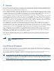
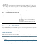
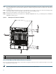
Figure 1 Cisco RF Gateway 10 chassis components - Front and Rear View 3 4 2 271377 1 7 5 6 1 Universal RF line card slots 2 Supervisor card slots 3 LCD/Pushbutton panel 4 Fan assembly 5 TCC / DTI card slots 6 DC PEM modules 7 RF Switch Cards/Coaxial cable termination slots 3
2 Site Preparation Do not unpack the chassis until you are ready to install it. Keep the chassis in the shipping container to prevent accidental damage until you determine an installation site. Before you install the Cisco RFGW-10, review the following: • The environmental conditions your installation site must meet to maintain normal operation. • The power requirements that must be in place at your installation site. • The cabling requirements for your installation site. • Rack-mounting requirements.
3 Chassis Installation The Cisco RFGW-10 UEQAM is shipped with all ordered (configured) components installed in the chassis. A fully configured Cisco RFGW-10 UEQAM (configured for redundancy support, including 10 RF line cards) weighs approximately 275 lbs. The chassis alone weighs 91 lbs. The chassis with the fan tray, TCC cards, and all RF switch cards weighs 138 lbs. It is not recommended that the Cisco RFGW-10 system be installed with all components in the system.
• Always install the heavier equipment in the lower half of the rack to maintain a low center of gravity to prevent the rack from falling over. • Install and use the cable-management brackets included with the Cisco RFGW-10 UEQAM to keep the cables organized and out of the way of the cards and processors.
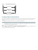
Figure 2 Verifying Equipment Rack Dimensions Mounting flanges Hole centerline to hole centerline 18.31 inches ± 0.06 inches (46.5 cm ± 0.15 cm) 28014 Minimum usable aperture 17.7 inches (45.0 cm) Installing the Chassis Installation Brackets Each chassis is shipped with two chassis installation brackets in the accessory kit.
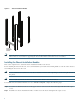
Chassis Installation Bracket 273445 Figure 3 Chassis installation bracket Note After the chassis is installed and secured to the rack, the chassis installation brackets can be removed from the rack. The brackets are not needed for supporting the chassis when all the rack-mount screws are installed. Installing the Chassis Installation Handles This section explains how to attach the chassis installation handles to the chassis.
Ensure that the captive screws are secured tightly prior to loading the handles to prevent injury or damage to the chassis. Figure 4 Attaching the Chassis Installation Handles to the Cisco RFGW-10 UEQAM 273450 Caution After the chassis rack-mount brackets are installed, additional handles can be installed onto the front of the rack-mount brackets. The rack-mount brackets allow a low and high installation of the handles onto the bracket depending on the chassis installation (low or high in the rack).
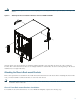
Step 1 Locate the threaded holes on the front sides of the chassis that align with the holes in the rack-mount bracket. Ensure that you hold the front rack-mount bracket with the ear and holes facing outward and towards the front of the chassis (see Figure 5). Step 2 Install all six M5 undercut flat head screws (provided in the accessory kit) to secure each of the rack-mounting bracket to the chassis. Three screws are installed on each end of the rack-mounting bracket.
To install the rack-mount brackets for a mid-mounted configuration on a Cisco RFGW-10 UEQAM, complete the following steps: Step 1 Locate the threaded holes on the middle sides of the chassis that align with the holes in the rack-mount bracket. Ensure that you hold the front rack-mount bracket with the ear and holes facing outward and towards the rear of the chassis (see Figure 6).
Warning To prevent bodily injury when mounting or servicing this unit in a rack, you must take special precautions to ensure that the system remains stable. The following guidelines are provided to ensure your safety: - This unit should be mounted at the bottom of the rack if it is the only unit in the rack. - When mounting this unit in a partially filled rack, load the rack from the bottom to the top with the heaviest component at the bottom of the rack.
Positioning the Chassis on the Chassis Installation Bracket 273447 Figure 8 Step 5 Remove the side chassis installation handles and slide the chassis into position in the rack. Note If you have the chassis installation handles installed on the front rack-mount rails they can be used to aid in sliding the chassis into the rack. Additionally, the fan tray handles can be used during the rack installation process.
Figure 9 Positioning the Chassis on the Rack 273448 Fan tray handle Step 7 Hold the chassis in position against the mounting rails and follow these steps: a. Insert a bottom screw into the rack-mount ear on each side and use a hand-held screwdriver to tighten the screw to the rack rail. Tip In the next step, insert the top screw diagonally from the bottom screw that you just attached.This helps in keeping the chassis in place. b.
Securing the Side Rack-Mount Brackets 273449 Figure 10 You can install your Cisco RFGW-10 chassis in a two-post rack (see Two-Post Rack Installation Mid-Mounted, page 15) or a four-post rack. Two-Post Rack Installation Mid-Mounted The Cisco RFGW-10 chassis can be installed in a two-post 19 inch rack either as a front mount or a mid-mount.
Installing the Cisco RFGW-10 in a Two-Post Equipment Rack Caution If you are using a two-post rack, secure the rack to the floor surface to prevent tipping and avoid bodily injury and component damage. 273881 Figure 11 Step 1 On the chassis, ensure that all the screw fasteners on the installed components are securely tightened. Step 2 Ensure that your path to the rack is unobstructed. If the rack is on wheels, ensure that the brakes are engaged or that the rack is otherwise stabilized.
Chassis Installation Bracket Chassis installation bracket 273675 Figure 12 Step 4 With two people, lift the chassis (partially unloaded) into position between the rack posts and rest it on the chassis installation bracket. Step 5 Position the chassis until the rack-mounting flanges flush against the mounting rails on the rack. Step 6 Hold the chassis in position against the mounting rails and follow these steps: a.
Recommended Tools and Supplies Table 2 lists the recommended tools and supplies. Table 2 Recommended Tools and Supplies Quantity Description Comments 1 Number 2 Phillips screwdriver — 1 Wire-stripping tool — 1 Crimping tool This tool must be large enough to accommodate the girth of the grounding lug when you crimp the grounding cable into the lug. 1 2-hole chassis grounding lug Included in the accessory kit. The 90 degree grounding lug has two M5 holes spaced 0.63 in center to center.
4 Connecting Cables This section describes how to do the cabling in the Cisco RFGW-10 UEQAM. Power and Ground Connections Each DC PEM has an earth ground connection and two DC power input connections (Input 1 and Input 2). Both external DC inputs must be connected as shown in Figure 13. Input 1 and Input 2 are individual power inputs. Both power inputs on the PEM must be wired to external power for the Cisco RFGW-10 to operate properly.
Step 1 Connect one end of the RJ-45 crossover cable to the RJ-45 port (labeled CONSOLE) on the supervisor. Step 2 Connect the other end of the cable to the appropriate port on the PC or terminal to complete the console port cable connection. Management Port The management port provides an Ethernet port to a LAN for a 10BASE-T and 100BASE-T connection for network management. Step 1 Connect one end of the RJ-45 Ethernet cable to the RJ-45 port (labelled Management on the supervisor card).
The T-10 TORX driver tool and a 1/4-inch flathead screwdriver are used to remove and install the cable bar clamp on the UCH, and loosen the line card captive screws. The Cisco RFGW-10 UEQAM coaxial cable interface uses 75-ohm precision miniature video cable bundled cables terminated to 75-ohm MCX connectors. The cables come in bundles of five that will fit into the provided rear RF cable management bracket.
Description Part Numbers Cisco RFGW-10 RF switch line card Cable kit (3m MCX to F RFGW-10-RFSW1 cables)1 CAB-RFSW520QTPMF, Cisco Systems, Inc. Quad-shielded 5x 5 bundle cable kit, 3 bundles with colors R,W,B,G,Y and 2 with colors Vi,O,Bk,Gr,Br. This cable kit will wire 2 RF switch cards of the 12.
Figure 16 Nominal Attenuation Graph for 75-Ohm Miniature Headend Coaxial Cable NOM ATTENUATION GRAPH 0 ATTEN (dB/100-FT) -2 -4 -6 -8 -10 -12 100 200 300 400 500 600 FREQ (MHz) 700 800 900 1000 NOM ATTEN (dB/10-0-ft) 82784 0 Installing the UCH on the Cisco RFGW-10 UEQAM RF Switch Card Caution The UCH must be used for all cable connections to the RF switch line card.
Figure 17 Aligning the UCH with the RF switch card Dense Connector Ports 273863 Cutout Shroud Red line Lead screw Installing the UCH on the Faceplate 273864 Figure 18 Step 5 Repeat steps 1 through 4 for the remaining 11 UCH to RF switch card interconnects. Note The RF switch cards connect orthogonally across all Universal RF line cards in the system picking up one connector off each card.
Tools and Equipment The tools listed below are designed to help you remove and install the cables in the UCH2. • T-10 TORX driver tool—Removes the cable clamp bar Note Do not use heat-shrink wrap on quad-shielded cables. • Cables—75-ohm quad-shielded precision miniature video cable, bonded foil 1855 type (reference YR50386 and YR52310, Belden five pack bundles) Installing Cables Cisco cables are color-coded for easy reference and installation. The cable color corresponds to a specific port on the card.
Removing an ESD Cap from a MCX connector Figure 20 Removing an ESD Cap from an F connector 155825 155824 Figure 19 Step 4 Insert and wiggle the connector into the hole. Placing Cables in the UCH2 273242 Figure 21 Note The cables fit loosely in the holes, and are not locked into place until the lock bar is closed (Step 6). Step 5 Repeat Step 3 and Step 4 for the remaining cables you are installing.
Note Make sure the cables are aligned correctly and inserted completely otherwise the slide bar will not close. Step 6 Slide the lock bar close completely, and use the T-10 TORX driver tool to tighten the screws clockwise (torque 10 in-lbs, 1.13 Newton meters (Nm)). The locking bar is completely closed when they are interlocked with the metal by the lead screw. Note Clamp bar maximum torque 15 in-lbs (1.
5 Powering on the Cisco RF Gateway 10 After all network interfaces and coaxial cables are connected, perform a visual check of all connections and ensure the following: • All captive screws on all line cards and modules should be tightened to 6-8 in-lbs. Note The system will not power on unless the captive screws on the DC PEM are fully engaged. • The ejector levers on every card are in the locked position. • All the cables are connected (power, data link, network, Ethernet).
Figure 22 DC PEM LEDs 1 5 6 2 7 3 1 273687 4 8 1 DC PEM captive screws 5 Fan 2 DC PEM On (|) /Off (O) switch 6 DC PEM handle 3 Earth grounding symbol 7 DC PEM LEDs 4 DC PEM earth ground lug 8 DC PEM terminal and plastic cover Note With both the DC PEMs installed, both need to be operating with breaker switches on and OUTPUT OK LED on.
6 Configuring the Cisco RF Gateway 10 at Startup This section describes how to configure the Cisco RFGW-10 UEQAM the first time. Entering the Initial Configuration Information To set up the Cisco RFGW-10 UEQAM, you need to assign an IP address and other configuration information necessary for the switch to communicate with the local routers and the Internet. The minimal configuration provided here does not cover feature configuration.
Configure System Management? [yes/no]: no Step 8 If you want to access the router using SNMP, enter Yes at the prompt: Configure SNMP Network Management? [yes]: yes Step 9 Specify an SNMP community string. Community string [public]: public Using Configuration Mode to Configure Your Switch To configure your switch from configuration mode, use the following procedure: Step 1 Connect a console terminal to the console interface of your supervisor card.
Switch(config)# ip default-gateway 172.20.52.35 Switch(config)# end 3d17h: %SYS-5-CONFIG_I: Configured from console by console Switch# show ip route Default gateway is 172.20.52.
Note If the enable password and enable secret commands are both set, you must enter the secret password. When you enter either of these password commands with the level option, you define a password for a specific privilege level. After you specify the level and set a password, give the password only to the users who need to have access at this level. Use the privilege level configuration command to specify commands accessible at various levels.
7 Troubleshooting The following section provides troubleshooting tips that you can use to verify your system setup. Before You Call for Technical Assistance If you are unable to solve the problem easily, contact a Cisco customer service representative for assistance and further instructions. See the “Obtaining Documentation and Submitting a Service Request” section on page 35.
8 Obtaining Documentation and Submitting a Service Request For information on obtaining documentation, submitting a service request, and gathering additional information, see the monthly What’s New in Cisco Product Documentation, which also lists all new and revised Cisco technical documentation, at: http://www.cisco.com/en/US/docs/general/whatsnew/whatsnew.
9 Related Documents • Cisco RF Gateway 10 Hardware Installation Guide http://www.cisco.com/en/US/docs/cable/rf_gateway/installation/guide/rfgw10_hig.html • Cisco RF Gateway 10 Command Reference Guide http://www.cisco.com/en/US/docs/cable/rf_gateway/command/reference/RFGW-10_Book.
Americas Headquarters Asia Pacific Headquarters Europe Headquarters Cisco Systems, Inc. San Jose, CA Cisco Systems (USA) Pte. Ltd. Singapore Cisco Systems International BV Amsterdam, The Netherlands Cisco has more than 200 offices worldwide. Addresses, phone numbers, and fax numbers are listed on the Cisco Website at http://www.cisco.com/web/siteassets/contacts/offices/index.html.