Cisco Video Surveillance 2600 IP Camera User Guide Model CIVS-IPC-2600 Americas Headquarters Cisco Systems, Inc. 170 West Tasman Drive San Jose, CA 95134-1706 USA http://www.cisco.
NOTICE. ALL STATEMENTS, INFORMATION, AND RECOMMENDATIONS IN THIS MANUAL ARE BELIEVED TO BE ACCURATE BUT ARE PRESENTED WITHOUT WARRANTY OF ANY KIND, EXPRESS OR IMPLIED. USERS MUST TAKE FULL RESPONSIBILITY FOR THEIR APPLICATION OF ANY PRODUCTS. THE SOFTWARE LICENSE AND LIMITED WARRANTY FOR THE ACCOMPANYING PRODUCT ARE SET FORTH IN THE INFORMATION PACKET THAT SHIPPED WITH THE PRODUCT AND ARE INCORPORATED HEREIN BY THIS REFERENCE.
Preface Overview This document, Cisco Video Surveillance IP Camera User Guide provides information about installing, configuring, using, managing, and troubleshooting the Cisco Video Surveillance 2600 IP Camera model, model CIVS-IPC-2600 Organization This manual is organized as follows: Chapter 1, “Overview” Provides an overview of the IP camera and its features Chapter 2, “Getting Started” Provides instructions for installing and performing the initial setup of the IP camera, connecting to the IP camer
Preface Cisco Video Surveillance 2600 IP Camera User Guide vi OL-24127-02
CONTENTS Preface v Overview v Organization v Obtaining Documentation, Obtaining Support, and Security Guidelines CHAPTER 1 Overview Features 1-1 1-1 IP Camera Overview 1-2 Physical Details 1-2 DC Auto Iris Lens Connector Pinouts Package Contents 1-6 CHAPTER 2 Getting Started 1-6 2-1 Installing the Cisco Video Surveillance IP Camera Performing the Initial Setup of the IP Camera Accessing the IP Camera Windows Powering the IP Camera On or Off Resetting the IP Camera Cleaning the IP Camera 3
Contents Audio/Video Windows 3-16 Video Window 3-16 Audio Window 3-23 Privacy Region Window 3-24 Security Windows 3-25 Product Process Window 3-25 Initialization Window 3-25 Complexity Window 3-26 Applications Windows 3-27 Mail & FTP Window 3-27 Motion Detection Window 3-29 Event Window 3-30 SNMP Window 3-33 Alarm I/O Ports Window 3-34 PTZ (RS-485) Window 3-35 Preset Positions Window 3-36 Status Windows 3-38 System Window 3-38 Audio/Video Window 3-39 Network Window 3-40 Syslog & Log Window 3-40 Video Log W
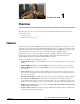
CH A P T E R 1 Overview This chapter provides an overview of the Cisco Video Surveillance IP Cameras and its features. It includes these topics: • Features, page 1-1 • IP Camera Overview, page 1-2 Features The Cisco Video Surveillance 2600 IP Camera offers a feature-rich digital camera solution for a video surveillance system. It provides high-quality, bandwidth-efficient video capture and transmission, with support for D1 resolution, motion-triggered viewing, H.264 encoding, and MPEG-4 encoding.
Chapter 1 Overview IP Camera Overview • Motion detection—The IP camera can detect motion in up to four designated fields of view by analyzing changes in pixels and generate an alert if motion is detected. • Flexible scheduling—You can configure the IP camera to respond to events that occur within a designated schedule. • Syslog support—The IP camera can send log data to a Syslog server.
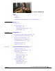
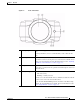
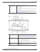
Chapter 1 Overview IP Camera Overview Figure 1-1 1 Front of IP Camera Lens opening The IP camera supports a variety of C and CS mount lenses, which attach here. For best performance, Cisco recommends that you use a DC auto iris lens. 2 Focus ring Allows you to adjust the back focus of the IP camera. You must loosen the focus ring hex screw on the bottom of the IP camera before you can rotate the focus ring. For instructions, see the “Adjusting Back Focus on the IP Camera” section on page 2-7.
Chapter 1 Overview IP Camera Overview 5 Ready LED (amber) Indicates power state as follows: • On—Power is on • Off—No power • Blinking—IP camera is starting up. The start up process takes 15 to 20 seconds. If you check the Enable LED Operations check box in the Basic Setup window, the Ready LED does not light. For more information see the “Basic Setup Window” section on page 3-5. Figure 1-2 and the table that follows describe the items on the rear of the IP camera.
Chapter 1 Overview IP Camera Overview 4 PoE LED (green) Indicates information about PoE as follows: • On—PoE connection is detected • Off—PoE connection is not detected 5 Analog video output BNC connector for video output (75 ohm). 6 Speaker output Allows the connection of an optional external speaker through a standard 3.5 mm mini phone jack. 7 Microphone input Allows the connection of an optional external microphone (with pre-amplifier) through a standard 3.5 mm mini phone jack.
Chapter 1 Overview IP Camera Overview DC Auto Iris Lens Connector Pinouts Figure 1-4 and the table that follows describe the pinouts of the DC auto iris lens connector on the IP camera. Figure 1-4 DC Auto Iris Lens Connector Pinouts Pin Function 1 Damp – 2 Damp + 3 Drive + 4 Drive – Package Contents The the Cisco Video Surveillance IP Camera package includes these items: • Cisco Video Surveillance 2600 IP Camera Quick Start Guide (qty.
CH A P T E R 2 Getting Started This chapter provides instructions for installing and performing the initial setup of the Cisco Video Surveillance IP Camera. It also describes how to access the IP camera through a web browser so that you can configure it or view video from it, and how to perform other important tasks.
Chapter 2 Getting Started Installing the Cisco Video Surveillance IP Camera Warning The power supply must be placed indoors. Statement 331 Note If you use the IP camera outdoors, place the camera and the power supply in a suitable NEMA enclosure. Warning This product requires short-circuit (overcurrent) protection, to be provided as part of the building installation. Install only in accordance with national and local wiring regulations.
Chapter 2 Getting Started Installing the Cisco Video Surveillance IP Camera Table 2-1 Installing the IP Camera (continued) Action Step 3 Explanation Optional. If you are going to connect a speaker and/or a A ferrite core must be attached to the speaker or microphone to the IP camera, attach a Snap-on ferrite microphone cable at approximately 10 inches (25 cm) core to the speaker and microphone cables. away from where the cable connects to the IP camera.
Chapter 2 Getting Started Performing the Initial Setup of the IP Camera Table 2-1 Installing the IP Camera (continued) Action Step 11 Explanation If you are using the IP camera on a network connection First, connect the bare wires at the end of the power that does not provide PoE, connect an external 12 V adapter to the terminal block that is provided with the IP power adapter.
Chapter 2 Getting Started Performing the Initial Setup of the IP Camera To make these configuration settings, you connect to the IP camera from any PC that is on the same network as the IP camera. The PC must meet these requirements: • Operating system—Microsoft Windows 2000, XP, or Vista • Browser—Internet Explorer 8.x or later In addition, you must know the IP address of the IP camera. By default, when the IP camera powers on, it attempts to obtain an IP address from a DHCP server in your network.
Chapter 2 Getting Started Accessing the IP Camera Windows • Click the Setup link to access configuration menus for the camera. For detailed information about these menus, see Chapter 3, “Configuring and Managing the IP Camera.” • Click the Home link to view and control live video from the camera. For detailed information about these actions, see Chapter 4, “Viewing Live Video.” • Click the Logout button to exit the window.
Chapter 2 Getting Started Adjusting Back Focus on the IP Camera • Enter the following for a secure connection if the IP address is 203.70.212.52 and the HTTPS port number is 1024: https://203.70.212.52:1024 • Enter the following for a non-secure connection if the IP address is 203.70.212.52 and the HTTP port number is 80: http://203.70.212.52 • Enter the following for a non-secure connection if the IP address is 203.70.212.52 and the HTTP port number is 1024: http://203.70.212.
Chapter 2 Getting Started Powering the IP Camera On or Off Powering the IP Camera On or Off The IP camera does not include an on/off switch. You power it on or off by connecting it to or disconnecting it from a power source. When you power off the IP camera, it retains configuration information. To power on the IP camera, take either of these actions: • Use an STP category 5 or higher network cable to connect the IP camera to a network switch that provides 802.
Chapter 2 Getting Started Cleaning the IP Camera Cleaning the IP Camera To clean and IP camera, follow these guidelines: • To clean the IP camera housing, use a clean, dry, soft cloth to gently wipe the surface of the housing • To clean the lens, use only tissue paper or solution that is designed for high quality optical lenses.
Chapter 2 Getting Started Cleaning the IP Camera Cisco Video Surveillance 2600 IP Camera User Guide 2-10 OL-24127-02
CH A P T E R 3 Configuring and Managing the IP Camera The Cisco Video Surveillance IP Camera provides configuration windows that you use to configure and manage the IP camera. This chapter explains how to access the configuration windows, describes each window, and provides detailed information about the options that are available in each window.
Chapter 3 Configuring and Managing the IP Camera Configuration Overview Table 3-1 Guidelines for Configuring the IP Camera Configuration Item Explanation Guidelines for Use Reference IP camera name and Identifies the IP camera. description Recommended. See the “Basic Setup Window” section on page 3-5. LED operation Determines whether the LEDs on the front of the IP camera light or remain off. Optional. See the “Basic Setup Window” section on page 3-5.
Chapter 3 Configuring and Managing the IP Camera Configuration Overview Table 3-1 Guidelines for Configuring the IP Camera (continued) Configuration Item Explanation Guidelines for Use Reference Audio options Includes options for audio Required if you use the internal See the “Audio Window” section streams that are received or sent or an external microphone, or an on page 3-23. by the IP camera. external speaker. Privacy regions Creates up to four user-defined Optional.
Chapter 3 Configuring and Managing the IP Camera Navigating the Configuration Windows Table 3-1 Guidelines for Configuring the IP Camera (continued) Configuration Item Explanation Guidelines for Use Reference Log file options Control which log information Recommended. the IP camera captures and whether it sends the log file to a Syslog server. See the “Syslog & Log Window” section on page 3-40. Video log options Let you manage the IP camera video log.
Chapter 3 Configuring and Managing the IP Camera Setup Windows • Security – Product Process – Initialization – Complexity • Applications – Mail & FTP – Motion Detection – Event – SNMP – Alarm I/O Ports – PTZ (RS-485) • Status – System – Audio Video – Network – Syslog & Log – Video Log Setup Windows The Setup windows let you configure a variety of basic and advanced settings for the IP camera, and to designate IP addresses that are allowed or denied access to the IP camera.
Chapter 3 Configuring and Managing the IP Camera Setup Windows Table 3-2 describes the options in the Basic Setup window. Table 3-2 Basic Setup Window Options Option Description Device Settings Device ID Display only. Unique identifier of the IP camera. The device ID is configured for the IP camera at the factory. Camera Name Enter a name for the IP camera. This name appears in the video log if an event occurs. (For related information, see the “Video Log Window” section on page 3-46.
Chapter 3 Configuring and Managing the IP Camera Setup Windows Table 3-2 Basic Setup Window Options (continued) Option Description NTP Port If you configured the IP camera to obtain its time from an NTP server, enter the NTP server port number. The default value is 123.
Chapter 3 Configuring and Managing the IP Camera Setup Windows Table 3-3 describes the options in the Advanced Setup window. Table 3-3 Advanced Setup Window Options Option Description CDP Enable CDP (Cisco Discovery Protocol) Check this check box if CDP is enabled in your network and you want the IP camera to send CDP discovery messages.
Chapter 3 Configuring and Managing the IP Camera Setup Windows Table 3-3 Advanced Setup Window Options (continued) Option Description Max RTP Video Packet Length Maximum number of bytes per video packet that are sent in each RTP request. Configure a lower number if you are streaming video to a cell phone that requires smaller data packets. Valid values are 400 through 1400. The default value is 1400. Max RTP Audio Packet Maximum number of bytes per audio packet that are sent in each RTP request.
Chapter 3 Configuring and Managing the IP Camera Setup Windows Table 3-3 Advanced Setup Window Options (continued) Option Description QoS Enable QoS Mode Check this check box and click the Audio, Video, or Both radio button to enable Quality of Service (QoS) for audio streams, video streams, or both streams. QOS applies to Layer 3 only, and is applied to ASF and RTP video streams.
Chapter 3 Configuring and Managing the IP Camera Setup Windows Table 3-4 IP Filter Window Options (continued) Option Description Single/Range If you enable IP address filtering, choose either of the following options from as many drop-down lists as needed: • Single—Enter an IP address that is denied or allowed access to the IP camera, depending on the Options setting. • Range—Enter a range of IP address that is denied or allowed access to the IP camera, depending on the Options setting.
Chapter 3 Configuring and Managing the IP Camera Administration Windows Table 3-5 EAPOL Window Options (continued) Option Description User ID User identifier that is used to log in to the RADIUS server. Password IP camera client log in password for the RADIUS server. Anonymous ID Unsigned public identifier to be used instead of a user name for logging in to the RADIUS server. PAC File Path and folder on this PC where the Protected Access Credential (PAC) file is stored.
Chapter 3 Configuring and Managing the IP Camera Administration Windows Table 3-6 describes the options in the Users window. Table 3-6 Users Window Options Option Description Administrator User ID Display only. The user ID for the IP camera administrator is Admin. The administrator can access the configuration windows for the IP camera, control all IP camera functions, view video from the IP camera, and access the Administrator windows User name Display only.
Chapter 3 Configuring and Managing the IP Camera Administration Windows Maintenance Window The Maintenance window provides options for resetting or restarting the IP camera, saving configuration information from the IP camera, and uploading the configuration information to the IP camera.
Chapter 3 Configuring and Managing the IP Camera Administration Windows Table 3-7 Maintenance Window Options (continued) Option Description Upload Path and folder where a configuration file is stored. You can click Browse to find this location. After you enter this information, click Upload and follow the on-screen prompts to load the configuration file to the IP camera. After you upload a configuration file to the IP camera, the IP camera restarts automatically.
Chapter 3 Configuring and Managing the IP Camera Audio/Video Windows Audio/Video Windows The Audio/Video windows provide options for configuring audio and video from the IP camera. The following sections describe the Setup windows in detail: • Video Window, page 3-16. • Audio Window, page 3-23 • Privacy Region Window, page 3-24 Video Window The Video window provides options for configuring the video from the IP camera.
Chapter 3 Configuring and Managing the IP Camera Audio/Video Windows Table 3-9 Video Window Options Option Description Streaming Mode Choose the mode that the IP camera uses for video streaming: • Single H.264 Stream—Configures H.264 for the primary stream. The stream can be up to D1 resolution and 30 fps. • Single MPEG-4 Stream—Configures MPEG-4 for the primary stream. The stream can be up to D1 resolution and 30 fps for NTSC or 25 fps for PAL.
Chapter 3 Configuring and Managing the IP Camera Audio/Video Windows Table 3-9 Video Window Options (continued) Option Description Max. Frame Rate Choose the desired maximum frame rate per second for the primary video stream from the IP camera. The default values are 30 for NTSC and 25 for PAL. A higher maximum frame rate provides better video quality but consumes more bandwidth H.264 Settings 2 Note These H.264 Settings 2 options appear if you choose the Dual H.
Chapter 3 Configuring and Managing the IP Camera Audio/Video Windows Table 3-9 Video Window Options (continued) Option Description Video Quality Control Choose an option for the video quality of the primary video stream from the IP camera: • Constant Bit Rate—Specifies that the video stream is output at or close to the constant bit rate that you choose. The default value is 4 Mbps. A higher bit rate provides better video quality but consumes more bandwidth.
Chapter 3 Configuring and Managing the IP Camera Audio/Video Windows Table 3-9 Video Window Options (continued) Option Description Fixed Video Quality Specifies that video is output at a fixed quality, which ranges from Very High to Very Low. The bit rate may vary to maintain this quality. The default fixed quality is Normal. A higher fixed quality provides better video quality but consumes more bandwidth. Max.
Chapter 3 Configuring and Managing the IP Camera Audio/Video Windows Table 3-9 Video Window Options (continued) Option Description Frame Repeat Count Designates how video output from the IP camera displays. The IP camera generates two independent fields (odd and even) for each video capture, which occur 60 times per second for NTSC or 50 times per second for PAL. When Frame Repeat Count is set to 1, the IP camera combines one odd and one even field to compose a video frame.
Chapter 3 Configuring and Managing the IP Camera Audio/Video Windows Table 3-9 Video Window Options (continued) Option Description Validation Time If the Switch Mode option is set to Auto, specify the time that the camera waits before switching Day/Night modes. The light level must continually exceed the threshold for the duration of the validation time to trigger a transition between the modes.
Chapter 3 Configuring and Managing the IP Camera Audio/Video Windows Audio Window The Audio window provides options for enabling and configuring audio that is transmitted to and from the IP camera. You can configure audio for these devices: • Internal microphone—The IP camera includes an internal microphone that can capture audio at the camera location. This audio is sent to the PC that you use to view video from the IP camera. You can listen to the audio when viewing video in the Home window.
Chapter 3 Configuring and Managing the IP Camera Audio/Video Windows Table 3-10 Audio Window Options (continued) Option Description Enable Microphone Display only. A check indicates that the internal microphone on the IP camera or an external microphone that is attached to the IP camera is enabled. The microphone is enabled when you check the Enable Audio check box and choose Simplex - Listen Only, Half Duplex - Talk or Listen, or Full Duplex - Talk and Listen.
Chapter 3 Configuring and Managing the IP Camera Security Windows Security Windows The Security windows provide options for stopping IP camera processes, configuring administrator and root password requirements, and enabling access to the IP camera through HTTP or Secure Shell (SSH) connections.
Chapter 3 Configuring and Managing the IP Camera Security Windows Table 3-13 describes the options in the Initialization window. Table 3-13 Initialization Window Options Option Description Admin Password Allows you to change the password for the IP camera administrator. The password is case sensitive and must contain at least 8 characters, which can be letters, numbers, and special characters, but no spaces. Special characters are: ! " # $ % & ' ( ) * + , - . : ; < = > ? @ [ \ ] ^ _ ` { | } ~.
Chapter 3 Configuring and Managing the IP Camera Applications Windows Applications Windows The Applications windows provide options for configuring and managing a variety of applications and IP camera activities. The following sections describe the Applications windows in detail: • Mail & FTP Window, page 3-27.
Chapter 3 Configuring and Managing the IP Camera Applications Windows To display the Mail & FTP window, access the configuration windows as described in the “Accessing the IP Camera Windows” section on page 2-6, click Applications, then click Mail & FTP. If you change any options in the Mail & FTP window, you must click Save to save the changes. To discard the changes, click Cancel before clicking Save. These buttons appear at the bottom of the window. You may need to scroll down to see them.
Chapter 3 Configuring and Managing the IP Camera Applications Windows Table 3-15 Mail & FTP Window Options (continued) Option Description E-mail Body Attach Video Streaming Check this check box to include in the message body the URL of an FTP URL Address server from which you can download a video file to your local PC. Primary FTP Primary FTP Check this check box to cause the IP camera automatically upload event video files to the primary FTP server when the files are created.
Chapter 3 Configuring and Managing the IP Camera Applications Windows If you change any options in the Motion Detection window, you must click Apply to save the changes. Note In addition to moving objects, motion detection can be triggered by rapid changes in lighting conditions or by movement of the IP camera itself. Table 3-16 describes the options in the Motion Detection window.
Chapter 3 Configuring and Managing the IP Camera Applications Windows When an event occurs, it triggers the IP camera to take certain configured actions. For example, an event can cause the IP camera to send a notification e-mail message to designated recipients and upload a video file to an SMTP server or an FTP server, or it can cause the IP camera to activate an output port. The Event window allows you to designate up to 10 schedules.
Chapter 3 Configuring and Managing the IP Camera Applications Windows Table 3-17 Event Window Options (continued) Option Description Actions Choose the desired options to designate actions that the camera takes when events occur: • E-Mail—Causes an e-mail message to be delivered to the SMTP server. The e-mail alerts users that an event has occurred, and may include a video file of the event and the URL of an FTP server from which users can download the video file.
Chapter 3 Configuring and Managing the IP Camera Applications Windows Table 3-17 Event Window Options (continued) Option Description Pre-Capture Length Length, in seconds, of additional video that is included in the video file immediately before the event. The default value is 0 (no pre-capture video). Post-Capture Length Length, in seconds, of additional video that is included in the video file immediately after the event. The default value is 5.
Chapter 3 Configuring and Managing the IP Camera Applications Windows Alarm I/O Ports Window The Alarm I/O Ports window allows you to configure various options for the two input and two output ports on the IP camera. A state change of an input ports triggers a camera to take configured actions. Output ports send relays that can control external devices, such as alarms or door switches.
Chapter 3 Configuring and Managing the IP Camera Applications Windows PTZ (RS-485) Window The PTZ (RS-485) window allows you to enable pan, tilt, zoom (PTZ) functions for the IP camera. These functions require that the IP camera be installed with a motorized zoom/focus lens in a pan/tilt mount that supports the Pelco D protocol. This window also provides options for configuring a patrol sequence, or sequence, for the IP camera.
Chapter 3 Configuring and Managing the IP Camera Applications Windows Table 3-20 PTZ (RS-485) Window Options (continued) Option Description Patrol Sequence Patrol Sequence Configure the order in which the IP camera executes preset operations. The preset list contains up to 9 positions that you configure as described in the “Preset Positions Window” section on page 3-36. The Sequence list specifies the order in which the IP camera goes to each preset position when you execute a sequence.
Chapter 3 Configuring and Managing the IP Camera Applications Windows Table 3-21 Preset Positions Window Options (continued) Option Description Navigation Keys Set the pan and tilt positions as follows: Focus Far button • To pan the IP camera, use the left or right arrow buttons • To tilt the IP camera, use the up or down arrow buttons • To move the IP camera to its home position, click the Move Camera Home button, which is located in the middle of the group of arrow keys Use these buttons to
Chapter 3 Configuring and Managing the IP Camera Status Windows Status Windows The Status windows provide options for viewing and managing a variety of system information. The following sections describe the Applications windows in detail: • System Window, page 3-38 • Audio/Video Window, page 3-39 • Network Window, page 3-40 • Syslog & Log Window, page 3-40 • Video Log Window, page 3-46 System Window The System window displays information about the IP camera.
Chapter 3 Configuring and Managing the IP Camera Status Windows Audio/Video Window The Audio/Video window displays information about the audio and video streams from the IP camera. You configure audio options as described in the “Audio Window” section on page 3-23. You configure video options as described in the “Video Window” section on page 3-16.
Chapter 3 Configuring and Managing the IP Camera Status Windows Network Window The Network window displays information about various IP camera network settings and operations. You configure the settings as described in the “Basic Setup Window” section on page 3-5. To display the Network window, access the configuration windows as described in the “Accessing the IP Camera Windows” section on page 2-6, click Status, then click Network.
Chapter 3 Configuring and Managing the IP Camera Status Windows Table 3-25 describes the options in the Syslog & Log window. Table 3-25 Syslog & Log Window Options Option Description Local Log Minimum Log Severity Choose the minimum severity of messages that the appear in the log file. The system logs all messages of this severity and higher. Message severities, from highest to lowest, are: • Emergency—The system is unusable. • Alert—A situation occurred that requires immediate action.
Chapter 3 Configuring and Managing the IP Camera Status Windows Table 3-25 Syslog & Log Window Options (continued) Option Description Minimum Log Severity Choose the minimum severity of messages that are sent to the Syslog server. The system sends all messages of this severity and higher. Message severities, from highest to lowest, are: • Emergency—The system is unusable. • Alert—A situation occurred that requires immediate action. • Critical—A situation occurred that requires action soon.
Chapter 3 Configuring and Managing the IP Camera Status Windows Table 3-26 Syslog and Log Information (continued) Message Explanation Audio: Disable microphone. Captures information when audio devices are enabled or disabled in the Audio window. Audio: Disable speaker. Audio: Enable microphone. (audio type: G.711 A-Law) Audio: Enable microphone. (audio type: G.711 u-Law) Audio: Enable microphone. (audio type: G.726) Audio: Enable speaker. DHCP: Lease release successfully.
Chapter 3 Configuring and Managing the IP Camera Status Windows Table 3-26 Syslog and Log Information (continued) Message Explanation output: Failed to set output port Port_Number. Provides information when you configure the output: Set output port Port_Number to high OK. output ports on the IP camera. output: Set output port Port_Number to low OK. output: Set output port Port_Number to pulse OK. PTZ: Focus far. A user clicked the Focus Far button in the Home window. PTZ: Focus near.
Chapter 3 Configuring and Managing the IP Camera Status Windows Table 3-26 Syslog and Log Information (continued) Message Explanation Stream: RTSP stream started. [ip: Type, UDP: Address_1:Port_1 -> Address_2:Port_2, User] Provides information when an RTSP stream from the IP camera is initiated (RTSP stream started) or stopped (RTSP stream stopped). Stream: RTSP stream stopped. [ip: Type, UDP: Address_1:Port_1 -> Address_2:Port_2, User] Type is the type of stream (Video or Audio).
Chapter 3 Configuring and Managing the IP Camera Status Windows Table 3-26 Syslog and Log Information (continued) Message Explanation SMTP log messages. Note These messages appear if you enable the FTP Log option. SMTP: Error during the connection or timeout. [host: Address] SMTP: Invalid sender address. [host: Address] SMTP: POP before SMTP authentication failed. [host: Address] Provide information when the IP camera generates an e-mail alert and communicates with an SMTP server.
Chapter 3 Configuring and Managing the IP Camera Status Windows Table 3-27 describes the option in the View Video Log window. Table 3-27 Video Log Window Options Option Description Video Log Displays a list of video logs. Files are named Camera_name-Event_Name-yymmdd-hhmmss.xxx, where: • Camera_name is the name of the IP camera, as configured in the Camera Name field in the Basic Setup window. • Event_name describes the event that caused the alert.
Chapter 3 Configuring and Managing the IP Camera Status Windows Cisco Video Surveillance 2600 IP Camera User Guide 3-48 OL-24127-02
CH A P T E R 4 Viewing Live Video After you install and set up the Cisco Video Surveillance IP Camera as described in Chapter 2, “Getting Started,” users can connect to the IP camera through Internet Explorer and access the Home window to view live video from the IP camera. The home window also provides for controlling the video display and certain IP camera functions. Available controls depend on the user type or privilege level.
Chapter 4 Viewing Live Video Viewing Video through the Home Window Overview Figure 4-1 Home Window 1 Digital zoom controls. For detailed information, see the “Home Window Controls” section on page 4-3. 2 IP camera date and time. You configure the date and time for the IP camera as described in the “Basic Setup Window” section on page 3-5. 3 Audio controls. For detailed information, see the “Home Window Controls” section on page 4-3. 4 Snapshot controls.
Chapter 4 Viewing Live Video Viewing Video through the Home Window Overview Home Window Controls The Home window provides controls for several IP camera features. Table 4-1 describes the controls in the Home window. Note The IP camera administrator and users with the administrator or monitor privilege can access all IP camera, video display, and audio controls. Users with the viewer privilege can access video display and audio controls only.
Chapter 4 Viewing Live Video Viewing Video through the Home Window Overview Table 4-1 Home Window Controls (continued) Control Description Microphone Off toggle button Click the Microphone Off button to mute the audio stream that is captured and sent to the IP camera from the internal or external microphone of the PC that you are using. When you click this button, the speaker that is attached to the IP camera does not play audio that is transmitted from your PC.
Chapter 4 Viewing Live Video Viewing Video through the Home Window Overview Table 4-1 Home Window Controls (continued) Control Description Preset Camera View drop-down list When you choose a preset position from this list, the camera immediately goes to that preset position. If the camera is executing a patrol sequence, choosing a preset position from this list cancels the sequence. This button appears only if you enabled external PTZ for the camera.
Chapter 4 Viewing Live Video Viewing Video through Third-Party Devices or Software Table 4-1 Home Window Controls (continued) Control Description Night button Improves video quality when the IP camera captures video in dark conditions. This button appears only if you configure the Day/Night Vision Switch Mode to Day or Night. For more information, see the “Video Window” section on page 3-16.
Chapter 4 Viewing Live Video Viewing Video through Third-Party Devices or Software Accessing the Primary H.264 Stream In the following commands, the ip_address argument represents the IP address of the IP camera. After you enter the command, enter your IP camera user name and password when prompted. • To access the primary H.264 stream with video and audio, enter this command: rtsp://ip_address/img/h264media.sav • To access the primary H.
Chapter 4 Viewing Live Video Viewing Video through Third-Party Devices or Software Accessing the MJPEG Stream In the following commands, the ip_address argument represents the IP address of the IP camera. After you enter the command, enter your IP camera user name and password when prompted. • To access the MJPEG stream with video and audio, enter this command: rtsp://ip_address/img/jpgmedia.sav • To access the MJPEG stream with video only, enter this command: rtsp://ip_address/img/jpgvideo.
CH A P T E R 5 Troubleshooting This chapter describes some common problems that may be encountered while using the IP camera and provides possible solutions. Symptom Cannot connect to an IP camera through a web browser.
Chapter 5 Troubleshooting Symptom The motion detection feature does not send e-mail alerts. Possible Cause The e-mail alert feature is not properly configured or the SMTP server that the IP camera uses to send the e-mail may be filtering e-mail to prevent spam from being sent from your server. Recommended Action Configure e-mail alerts as described in the “Basic Setup Window” section on page 3-5, the “Mail & FTP Window” section on page 3-27, and the “Event Window” section on page 3-30.
A P P E N D I X A Using the IP Camera with Cisco VSM Cisco Video Surveillance Manager (VSM) is a suite of powerful and flexible video surveillance applications that interoperate with a wide range of devices and cameras to provide a complete, standards-based video surveillance solution. VSM consists of modules to manage, archive, view, and distribute video.
Appendix A Using the IP Camera with Cisco VSM Cisco Video Surveillance 2600 IP Camera User Guide A-2 OL-24127-02
INDEX Audio/Video windows A 3-16 Audio window action options configuring overview 3-32 overview 3-31 3-31 ActiveX controls 3-29 activity indication 1-3 day to night threshold described validation time 3-13 description 3-12 back focus adjusting setting 5-1 3-13 3-6 3-5 Baud rate, for PTZ Alarm I/O Ports window bit rate, of video 3-34 3-35 3-17, 3-19 Bonjour, enabling on camera 3-34 analog video display Applications windows brightness, of video 3-8 3-20 2-3 3-27 C audio co
Index cleaning, IP camera C mount lens options 2-9 overview 1-3, 2-2 codec, for audio 3-24 Complexity window options 3-26 overview 3-1 3-1 requirements 3-1 configuration, of IP camera backing up Product Process window 3-25 3-5 SNMP window 3-33 Status windows 3-38 3-40 3-38 3-1 3-12 Video Log window 3-14 Video window 3-46 3-16 connecting, to the IP camera after the first time 3-15 configuration windows for the first time 2-6 2-4 PC requirements for 2-6 3-12 Advanced Setup
Index night schedule mode described actions 3-21 end time 3-31 interval before triggering daylight saving time, adjustment for day mode, day/night vision notification of 3-6 overview 3-21 day to night threshold, day/night vision auto mode video of 1-3 connector pinouts 3-27 options 3-6 DHCP, obtaining IP address through Disable Iris button 3-31 Event window 1-6 description, for IP camera 3-27 3-31 trigger types connecting 3-32 3-27, 3-30 scheduling 3-22 DC auto iris lens 3-3
Index overview G 3-25 input device, connecting gateway, for IP camera 3-7, 3-40 input ports General purpose input/output (GPIO) port 1-5 connecting devices to event trigger state H 1-5 state change 3-30 3-34 analog video display 3-39 half duplex control device 3-23 hardware version, of IP camera Home link, in Main window 3-38 2-6, 2-7 configuring 4-5 Home window 4-3 4-2 overview 2-1 2-3 controlling access by 3-10 default for IP camera 2-5, 2-6 fixed 2-6 controls in 3-7 o
Index LAN port on lens 1-4 L 1-3, 2-2 locking down mounting name LAN port 2-4 LED 2-4 Activity 3-6 overview package contents 1-6 4-5 power connection 1-5 disabling 3-6 enabling 3-6 Network 1-4 powering off 2-8 PoE powering on 2-8 Ready resetting restoring factory default configurations tilting 1-3, 2-2 for IP camera time zone type 3-6 troubleshooting user types zoom optical 3-37, 4-5 4-6 4-1 FTP 2-4 3-45 SMTP 3-46 system 3-42 log file clearing 3-42 storage
Index audio port M enabling MAC address, of IP camera 3-38 video port 3-28 overview 3-9 3-9 muting 3-27 PC microphone Maintenance window options 3-9 video address Mail & FTP window options 3-9 PC speaker 4-4 4-3 3-14 overview 3-14 N Main window description 2-5, 2-7 name, of IP camera Home link 2-6, 2-7 network Logout button Setup link 2-6, 2-7 activity 2-6, 2-7 type microphone 1-4 3-40 Network LED enabling 3-24 external 1-5, 3-23 1-4 Network window installing ex
Index Preset Positions window P options package contents 1-6 overview pan, tilt, zoom color 4-5 pan speed 3-24 enabling 3-37 3-24 Privacy Region window parity, for PTZ 3-35 options password 3-24 overview complexity 3-26 for Administrator user type for primary FTP server 3-26 stopping for secondary FTP server 3-29 for secondary SMTP server for User user type descriptions 3-29 3-28 options 3-28 3-25 Baud rate 2-5, 3-13 3-35 configuring data bits 1-6 pan speed 1-5 parity
Index reset primary factory default values IP address Reset button secondary 2-8 3-28 snapshot, of video image 2-8 SNMP, configuring 1-4 resetting the IP camera restarting, IP camera root password 3-26 RTP data port 3-8 4-4 3-33 SNMP window 1-4 options 3-14 restoring, factory default configurations RTSP port 3-28 3-33 overview 3-14 3-33 speaker 3-8 enabling 3-24 external 1-5, 3-23 installing 2-3 SSH, allowing access through S 3-26 start time, day/night vision night sch
Index administrator password recovery alerts quality 5-1 5-2 cannot access IP camera through browser motion detection 5-1 3-17, 3-19 resolution 3-17, 3-18 saturation 3-20 secondary stream 5-2 sharpness U Unique Device Identifier (UDI) upgrading firmware stream 1 settings 3-17, 3-18 stream 2 settings 3-18, 3-19 3-21 time stamp on 3-15 3-21 viewing live user name for Administrator user type requirements for through Home window 3-13 options overview video file deleting 3-12 3-47
Index of audio from camera of PC microphone of PC speaker 4-3 4-4 4-3 W white balance, preset modes 3-20 Z zoom digital 4-3 optical 3-36, 4-5 Cisco Video Surveillance 2600 IP Camera User Guide IN-10 OL-24127-02