Cisco Video Surveillance 2630 IP Dome User Guide Model CIVS-IPC-2630V Americas Headquarters Cisco Systems, Inc. 170 West Tasman Drive San Jose, CA 95134-1706 USA http://www.cisco.
NOTICE. ALL STATEMENTS, INFORMATION, AND RECOMMENDATIONS IN THIS MANUAL ARE BELIEVED TO BE ACCURATE BUT ARE PRESENTED WITHOUT WARRANTY OF ANY KIND, EXPRESS OR IMPLIED. USERS MUST TAKE FULL RESPONSIBILITY FOR THEIR APPLICATION OF ANY PRODUCTS. THE SOFTWARE LICENSE AND LIMITED WARRANTY FOR THE ACCOMPANYING PRODUCT ARE SET FORTH IN THE INFORMATION PACKET THAT SHIPPED WITH THE PRODUCT AND ARE INCORPORATED HEREIN BY THIS REFERENCE.
CONTENTS Preface vii Overview 1-vii Organization 1-vii Obtaining Documentation, Obtaining Support, and Security Guidelines CHAPTER 1 Overview Features 1-vii 1-1 1-1 IP Camera Overview 1-2 Physical Details 1-3 Package Contents 1-6 CHAPTER 2 Getting Started 2-1 Before You Begin 2-1 Installing the Cisco Video Surveillance 2630 IP Dome Preparing for Installation 2-2 Mounting with a Conduit Base 2-4 Mounting with a Pendant 2-9 Performing the Initial Setup of the IP Camera Accessing the IP Came
Contents Users Window 3-12 Maintenance Window 3-14 Firmware Window 3-15 Audio/Video Windows 3-16 Video Window 3-16 Audio Window 3-23 Privacy Region Window 3-24 Focus/Zoom Window 3-24 Security Windows 3-25 Initialization Window 3-25 Complexity Window 3-26 Applications Windows 3-27 Mail/FTP/HTTP Window 3-27 Motion Detection Window 3-30 Event Window 3-31 SNMP Window 3-34 Alarm I/O Ports Window 3-35 Status Windows 3-36 System Window 3-36 Audio/Video Window 3-37 Network Window 3-38 Syslog & Log Window 3-38 Vide
Preface Overview This document, Cisco Video Surveillance 2630 IP Dome User Guide, provides information about installing, configuring, using, managing, and troubleshooting the Cisco Video Surveillance 2630 IP Dome, model CICS-IPC-2630V.
Preface Obtaining Documentation, Obtaining Support, and Security Guidelines Cisco Video Surveillance 2630 IP Dome User Guide viii OL-24130-02
CH A P T E R 1 Overview This chapter provides an overview of the Cisco Video Surveillance 2630 IP dome and its features. It includes these topics: • Features, page 1-1 • IP Camera Overview, page 1-2 Features The Cisco Video Surveillance IP cameras offer a feature-rich digital camera solution for a video surveillance system. They provide high-quality, bandwidth-efficient video capture and transmission, with support for D1 resolution, motion-triggered viewing, H.264 encoding, and MPEG-4 encoding.
Chapter 1 Overview IP Camera Overview • Motion detection—The IP cameras can detect motion in up to four designated fields of view by analyzing changes in pixels and generate an alert if motion is detected. • Flexible scheduling—You can configure the IP cameras to respond to events that occur within a designated schedule. • Syslog support—The IP cameras can send log data to a Syslog server.
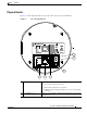
Chapter 1 Overview IP Camera Overview Physical Details Figure 1-1 and the table that follows describe the items on the top of the 2630 IP dome.
Chapter 1 Overview IP Camera Overview 3 Audio port Allows the connection of the audio Y cable that is provided with the IP camera. You can connect an optional external speaker, optional external microphone (with pre-amplifier), or both devices through this cable. Each device connects to the audio cable through a standard 3.5 mm mini phone jack. A speaker connects to the green jack, which is labeled “Audio Out.” A microphone connects to the pink jack, which is labeled “Audio In.
Chapter 1 Overview IP Camera Overview Figure 1-2 and the table that follows describe the items on the bottom of the 2630 IP dome. Figure 1-2 Bottom of the 2630 IP Dome 1 5 4 3 2 1 USB port Reserved for future use 2 Analog video output 3.5 mm video jack for video output to an analog monitor. 3 Reset button Recessed button that reboots the IP camera or resets it to a default state. You can use a pin or paper clip to depress it.
Chapter 1 Overview IP Camera Overview 4 5 Network LED (amber) Power LED (green) Indicates information about the network connections as follows: • On—LAN connection is detected • Off—LAN connection is not detected • Blinking—Data is being transmitted or received via the LAN connection Lights for approximately 1 minute when the camera powers up, then turns off.
CH A P T E R 2 Getting Started This chapter provides instructions for installing and performing the initial setup of the Cisco Video Surveillance IP Camera. It also describes how to access the IP camera through a web browser so that you can configure it or view video from it, and how to perform other important tasks.
Chapter 2 Getting Started Installing the Cisco Video Surveillance 2630 IP Dome Warning The power supply must be placed indoors. Statement 331 Note If you use the IP camera outdoors, place the camera and the power supply in a suitable NEMA enclosure. Warning This product requires short-circuit (overcurrent) protection, to be provided as part of the building installation. Install only in accordance with national and local wiring regulations.
Chapter 2 Getting Started Installing the Cisco Video Surveillance 2630 IP Dome • Run a power cable from a 24 VAC power adapter to the mounting location. Use a cable gauge that is appropriate for the distance from the IP dome to the power supply (consult a qualified electrician for more information). The terminal connectors on the IP dome support gauges from 14 AWG to 24 AWG. At the end of the wire that attaches to the IP dome, strip enough cable housing to allow each wire to be stripped to 1/4 inch (6.
Chapter 2 Getting Started Installing the Cisco Video Surveillance 2630 IP Dome Mounting with a Conduit Base You can mount the 2630 IP dome with an optional conduit base (CIVS-IPCA-1006=) in situations where you cannot cut a hole through a surface for cables or where cables run through a small hole in a surface.
Chapter 2 Getting Started Installing the Cisco Video Surveillance 2630 IP Dome 3 Camera unit screws (2) 4 Privacy shield 5 Dome assembly 6 TORX security screws (3) Step 2 Remove the Privacy shield by squeezing it inward to release it from the four tabs that hold it into place (see Figure 2-2).
Chapter 2 Getting Started Installing the Cisco Video Surveillance 2630 IP Dome Step 8 Note 1 Ceiling or wall 2 Rubber sheet 3 Conduit base Attach the base plate to the conduit base with the four screws, provided (see Figure 2-4). Make sure the that gasket is clean and in place.
Chapter 2 Getting Started Installing the Cisco Video Surveillance 2630 IP Dome To connect a power cable, use a flat-head screwdriver to depress the brown tabs on the power input and connect bare positive, negative, and ground wires as shown on the label that is affixed to the IP dome. Step 11 (Optional) Connect an external speaker, microphone, or both to the Y cable, then connect the Y cable to the audio port on the IP dome.(see Figure 1-1 on page 1-3).
Chapter 2 Getting Started Installing the Cisco Video Surveillance 2630 IP Dome Step 14 See Figure 2-13 on page 2-18 and take these actions to adjust the camera lens to obtain the desired image: • Temporarily attach an analog monitor to the IP dome so that you can see video while adjusting the camera. If the cable from the monitor terminates with a 3.5 mm jack, plug it into the analog video output port on the IP dome.
Chapter 2 Getting Started Installing the Cisco Video Surveillance 2630 IP Dome Figure 2-6 Step 16 Attaching the Privacy Shield and Dome Attach the dome assembly by aligning its tab with the opening in the base plate, pressing it into place, and securing the three TORX screws (see Figure 2-6). Make sure that the security strap that connects the dome assembly to the camera housing is in place. Mounting with a Pendant You can mount the 2630 IP dome to a wall or ceiling with an optional pendant.
Chapter 2 Getting Started Installing the Cisco Video Surveillance 2630 IP Dome Figure 2-7 Disassembling the 2630 IP Dome Components 1 2 3 4 5 6 Step 2 1 Base plate 2 Camera unit 3 Camera unit screws (2) 4 Privacy shield 5 Dome assembly 6 TORX security screws (3) Attach the pendant to a ceiling or wall with 4 screws, as shown in Figure 2-8. You can mount the pendant using the inside mounting holes or the outside mounting holes.
Chapter 2 Getting Started Installing the Cisco Video Surveillance 2630 IP Dome Figure 2-8 Step 3 Attaching the Pendant to a Ceiling or Wall Attach the conduit base to the pendant with 4 screws, as shown in Figure 2-9. Make sure the gasket on the pendant is in place and clean.
Chapter 2 Getting Started Installing the Cisco Video Surveillance 2630 IP Dome Step 4 Attach the base plate to conduit with 4 screws, provided, as shown in Figure 2-10. Make sure that the gasket is clean and in place.
Chapter 2 Getting Started Installing the Cisco Video Surveillance 2630 IP Dome Step 9 Attach the camera unit to the base plate by aligning the three tabs on the camera unit with the slots on the base plate, pressing the camera unit into the base plate until the tabs snap into place, and securing the camera unit with the two camera unit screws (see Figure 2-11).
Chapter 2 Getting Started Performing the Initial Setup of the IP Camera Step 11 Replace the privacy shield by squeezing it to fit inside the four tabs on the camera unit (see Figure 2-12). Make sure to adjust the privacy shield inside the dome and trim ring assembly so that it does not block the lens from capturing video.
Chapter 2 Getting Started Performing the Initial Setup of the IP Camera In addition, you must know the IP address of the IP camera. By default, when the IP camera powers on, it attempts to obtain an IP address from a DHCP server in your network. If the camera cannot obtain an IP address through DCHP within 90 seconds, it uses a default IP address of 192.168.0.100. To connect to the IP camera for the first time and make initial configuration settings, perform the following steps.
Chapter 2 Getting Started Accessing the IP Camera Windows Accessing the IP Camera Windows After you perform the initial configuration as described in the “Performing the Initial Setup of the IP Camera” section on page 2-14, follow the steps in this section each time that you want to access the IP camera windows to make configuration settings or view live video.
Chapter 2 Getting Started Adjusting the Video Image • Enter the following for a non-secure connection if the IP address is 203.70.212.52 and the HTTP port number is 1024: http://203.70.212.52:1024 Step 2 Enter your IP camera user name and password when prompted, then click OK. To log in as the IP camera administrator, enter the user name admin (all lower case) and the password that is configured for the administrator.
Chapter 2 Getting Started Adjusting the Video Image or away from the camera. Take care not to pull the lens completely away from the camera.Obtain a sharp picture in both wide-angle and telephoto positions. When the focus is set as desired, use the Allen wrench to tighten the back focus hex screw. Caution Do not manually adjust the focus or zoom for the IP camera. Attempting to manually do so may damage the IP camera lens.
Chapter 2 Getting Started Powering the IP Camera On or Off Powering the IP Camera On or Off The IP camera does not include an on/off switch. You power it on or off by connecting it to or disconnecting it from a power source. When you power off the IP camera, it retains configuration information. To power on the IP camera, connect the IP camera to a 24 VAC power source. To power off the IP camera, unplug the power source from the wall or disconnect it from the camera.
Chapter 2 Getting Started Cleaning the IP Camera Cisco Video Surveillance 2630 IP Dome User Guide 2-20 OL-24130-02
CH A P T E R 3 Configuring and Managing the IP Camera The Cisco Video Surveillance IP Camera provides configuration windows that you use to configure and manage the IP camera. This chapter explains how to access the configuration windows, describes each window, and provides detailed information about the options that are available in each window.
Chapter 3 Configuring and Managing the IP Camera Configuration Overview Table 3-1 Guidelines for Configuring the IP Camera Configuration Item Explanation Guidelines for Use Reference IP camera name and Identifies the IP camera. description Recommended. See the “Basic Setup Window” section on page 3-5. LED operation Determines whether the LEDs on the front of the IP camera light or remain off. Optional. See the “Basic Setup Window” section on page 3-5.
Chapter 3 Configuring and Managing the IP Camera Configuration Overview Table 3-1 Guidelines for Configuring the IP Camera (continued) Configuration Item Explanation Audio options Includes options for audio Required if you use an external streams that are received or sent microphone or speaker. by the IP camera. See the “Audio Window” section on page 3-23. Privacy regions Creates up to four user-defined Optional.
Chapter 3 Configuring and Managing the IP Camera Navigating the Configuration Windows Navigating the Configuration Windows After you access the configuration windows as described in the “Accessing the IP Camera Windows” section on page 2-16, a window appears that includes the following components: • Navigation tree—Appears at the left of the window and provides links to each configuration window • Basic Setup window—Appears at the right of the window The navigation tree always appears.
Chapter 3 Configuring and Managing the IP Camera Setup Windows • Status – System – Audio/Video – Network – Syslog & Log – Video Log Setup Windows The Setup windows let you configure a variety of basic and advanced settings for the IP camera, and to designate IP addresses that are allowed or denied access to the IP camera.
Chapter 3 Configuring and Managing the IP Camera Setup Windows Table 3-2 Basic Setup Window Options (continued) Option Description Description Enter a description of the IP camera. For example, enter the IP camera location, such as “North Entrance.” The description can include any combination of up to 32 letters, numbers, and spaces.
Chapter 3 Configuring and Managing the IP Camera Setup Windows Table 3-2 Basic Setup Window Options (continued) Option Description Network Settings Configuration Type Choose the option that indicates how the IP camera obtains its IP address: • Obtain Address Automatically (DHCP)—If your network includes a DHCP server for dynamic allocation of IP addresses, choose this option if you want DHCP to assign an IP address and subnet mask to the IP camera.
Chapter 3 Configuring and Managing the IP Camera Setup Windows Table 3-3 Advanced Setup Window Options Option Description CDP Enable CDP (Cisco Discovery Protocol) Check this check box if CDP is enabled in your network and you want the IP camera to send CDP discovery messages. Bonjour Enable Bonjour (Cisco Discovery Protocol) Check this check box if Bonjour is enabled in your network and you want the IP camera to send Bonjour discovery messages.
Chapter 3 Configuring and Managing the IP Camera Setup Windows Table 3-3 Advanced Setup Window Options (continued) Option Description Max RTP Video Packet Length Maximum number of bytes per video packet that are sent in each RTP request. Configure a lower number if you are streaming video to a cell phone that requires smaller data packets. Valid values are 400 through 1400. The default value is 1400. Max RTP Audio Packet Maximum number of bytes per audio packet that are sent in each RTP request.
Chapter 3 Configuring and Managing the IP Camera Setup Windows Table 3-3 Advanced Setup Window Options (continued) Option Description QoS Enable QoS Mode Check this check box and click the Audio, Video, or Both radio button to enable Quality of Service (QoS) for audio streams, video streams, or both streams. QOS applies to Layer 3 only, and is applied to ASF and RTP video streams.
Chapter 3 Configuring and Managing the IP Camera Setup Windows Table 3-4 IP Filter Window Options (continued) Option Description Single/Range If you enable IP address filtering, choose either of the following options from as many drop-down lists as needed: • Single—Enter an IP address that is denied or allowed access to the IP camera, depending on the Options setting. • Range—Enter a range of IP address that is denied or allowed access to the IP camera, depending on the Options setting.
Chapter 3 Configuring and Managing the IP Camera Administration Windows Table 3-5 EAPOL Window Options (continued) Option Description User ID User identifier that is used to log in to the RADIUS server. Password IP camera client log in password for the RADIUS server. Anonymous ID Unsigned public identifier to be used instead of a user name for logging in to the RADIUS server. PAC File Path and folder on this PC where the Protected Access Credential (PAC) file is stored.
Chapter 3 Configuring and Managing the IP Camera Administration Windows Table 3-6 describes the options in the Users window. Table 3-6 Users Window Options Option Description Administrator User ID Display only. The user ID for the IP camera administrator is Admin. The administrator can access the configuration windows for the IP camera, control all IP camera functions, view video from the IP camera, and access the Administrator windows User name Display only.
Chapter 3 Configuring and Managing the IP Camera Administration Windows Maintenance Window The Maintenance window provides options for resetting or restarting the IP camera, saving configuration information from the IP camera, and uploading the configuration information to the IP camera.
Chapter 3 Configuring and Managing the IP Camera Administration Windows Table 3-7 Maintenance Window Options (continued) Option Description Upload Path and folder where a configuration file is stored. You can click Browse to find this location. After you enter this information, click Upload and follow the on-screen prompts to load the configuration file to the IP camera. After you upload a configuration file to the IP camera, the IP camera restarts automatically.
Chapter 3 Configuring and Managing the IP Camera Audio/Video Windows Audio/Video Windows The Audio/Video windows provide options for configuring audio and video from the IP camera. The following sections describe the Audio/Video windows in detail: • Video Window, page 3-16. • Audio Window, page 3-23 • Privacy Region Window, page 3-24 • Focus/Zoom Window, page 3-24 Video Window The Video window provides options for configuring the video from the IP camera.
Chapter 3 Configuring and Managing the IP Camera Audio/Video Windows Table 3-9 Video Window Options Option Description Streaming Mode Choose the mode that the IP camera uses for video streaming: • Single H.264 Stream—Configures H.264 for the primary stream. The stream can be up to D1 resolution and 30 fps. • Single MPEG-4 Stream—Configures MPEG-4 for the primary stream. The stream can be up to D1 resolution and 30 fps for NTSC or 25 fps for PAL.
Chapter 3 Configuring and Managing the IP Camera Audio/Video Windows Table 3-9 Video Window Options (continued) Option Description Max. Frame Rate Choose the desired maximum frame rate per second for the primary video stream from the IP camera. The default values are 30 for NTSC and 25 for PAL. A higher maximum frame rate provides better video quality but consumes more bandwidth H.264 Settings 2 Note These H.264 Settings 2 options appear if you choose the Dual H.
Chapter 3 Configuring and Managing the IP Camera Audio/Video Windows Table 3-9 Video Window Options (continued) Option Description Video Quality Control Choose an option for the video quality of the primary video stream from the IP camera: • Constant Bit Rate—Specifies that the video stream is output at or close to the constant bit rate that you choose. The default value is 4 Mbps. A higher bit rate provides better video quality but consumes more bandwidth.
Chapter 3 Configuring and Managing the IP Camera Audio/Video Windows Table 3-9 Video Window Options (continued) Option Description Fixed Video Quality Specifies that video is output at a fixed quality, which ranges from Very High to Very Low. The bit rate may vary to maintain this quality. The default fixed quality is Normal. A higher fixed quality provides better video quality but consumes more bandwidth. Max.
Chapter 3 Configuring and Managing the IP Camera Audio/Video Windows Table 3-9 Video Window Options (continued) Option Description Frame Repeat Count Designates how video output from the IP camera displays. The IP camera generates two independent fields (odd and even) for each video capture, which occur 60 times per second for NTSC or 50 times per second for PAL. When Frame Repeat Count is set to 1, the IP camera combines one odd and one even field to compose a video frame.
Chapter 3 Configuring and Managing the IP Camera Audio/Video Windows Table 3-9 Video Window Options (continued) Option Description Validation Time If the Switch Mode option is set to Auto, specify the time that the camera waits before switching Day/Night modes. The light level must continually exceed the threshold for the duration of the validation time to trigger a transition between the modes.
Chapter 3 Configuring and Managing the IP Camera Audio/Video Windows Audio Window The Audio window provides options for enabling and configuring audio that is transmitted to and from the IP camera. You can configure audio for these devices: • External microphone—You can connect an optional external microphone (available from third-parties) to the IP camera. This audio is sent to the PC that you use to view video from the IP camera. You can listen to the audio when viewing video in the Home window.
Chapter 3 Configuring and Managing the IP Camera Audio/Video Windows Table 3-10 Audio Window Options (continued) Option Description Enable External Speaker Display only. A check indicates that a speaker that is connected to the IP camera is enabled. The speaker is enabled when you check the Enable Audio check box and choose Simplex - Talk Only, Half Duplex - Talk or Listen, or Full Duplex - Talk and Listen to make this check box available.
Chapter 3 Configuring and Managing the IP Camera Security Windows Table 3-12 Focus/Zoom Window Options Option Description Zoom Controls the lens zoom to change the field of view. Move the Zoom slider to the left for a wider field of view and to the right for a telescopic field of view. Note Focus Controls the lens focus to achieve a sharp image. Move the Focus slider to the left to focus on objects close to the IP camera and to the right to focus on more distant objects.
Chapter 3 Configuring and Managing the IP Camera Security Windows Table 3-13 Initialization Window Options Option Description Admin Password Allows you to change the password for the IP camera administrator. The password is case sensitive and must contain at least 8 characters, which can be letters, numbers, and special characters, but no spaces. Special characters are: ! " # $ % & ' ( ) * + , - . : ; < = > ? @ [ \ ] ^ _ ` { | } ~.
Chapter 3 Configuring and Managing the IP Camera Applications Windows Applications Windows The Applications windows provide options for configuring and managing a variety of applications and IP camera activities. The following sections describe the Applications windows in detail: • Mail/FTP/HTTP Window, page 3-27.
Chapter 3 Configuring and Managing the IP Camera Applications Windows If you change any options in the Mail/FTP/HTTP window, you must click Save to save the changes. To discard the changes, click Cancel before clicking Save. These buttons appear at the bottom of the window. You may need to scroll down to see them. Table 3-15 describes the options in the Mail/FTP/HTTP window.
Chapter 3 Configuring and Managing the IP Camera Applications Windows Table 3-15 Mail/FTP/HTTP Window Options (continued) Option Description E-mail Body Attach Video Streaming Check this check box to include in the message body the URL of an FTP URL Address server from which you can download a video file to your local PC. Primary FTP Primary FTP Check this check box to enable the IP camera automatically send event video files to the primary FTP server when the files are created.
Chapter 3 Configuring and Managing the IP Camera Applications Windows Table 3-15 Mail/FTP/HTTP Window Options (continued) Option Description URL Base Enter a string to be used as the prefix in the HTTP URL. The HTTP URL is sent in this format: http://ip-address/url-base?system-provided-name-value-pairs where: • ip-address is the IP address of the HTTP notification server, • url-base is the string that you enter for this field (URL Base).
Chapter 3 Configuring and Managing the IP Camera Applications Windows Table 3-16 Motion Detection Window Options Option Motion Detection Area Description • Motion Inclusion Regions—Create a window to designate an area to examine for motion. Select up to 4 check boxes to specify areas in the video. If desired, enter a name of up to 12 characters for each area in the field next to the corresponding check box. Drag the window to the desired area and drag an edge or corner of the window to resize it.
Chapter 3 Configuring and Managing the IP Camera Applications Windows If you change any options in the Event window, except deleting an event from the event schedule list, you must click Save to save the changes. To discard the changes, click Cancel before clicking Save. These buttons appear at the bottom of the window. You may need to scroll down to see them. Table 3-17 describes the options in the Event window.
Chapter 3 Configuring and Managing the IP Camera Applications Windows Table 3-17 Event Window Options (continued) Option Description Actions Choose the desired options to designate actions that the camera takes when events occur: • E-Mail—Sends e-mail event notification messages to an SMTP server. The e-mail messages notify you that an event has occurred, and may include a video file of the event and the URL of an FTP server from which you can download the video file.
Chapter 3 Configuring and Managing the IP Camera Applications Windows Table 3-17 Event Window Options (continued) Option Description Video Format (MPSG-4) Appears if you choose the Video option from the Attachment Type drop-down list. Choose the format (asf, mp4, or 3gp) for the video file of the event. If you choose mp4, or 3gp, video files do not include audio. Pre-Capture Length Length, in seconds, of additional video that is included in the video file immediately before the event.
Chapter 3 Configuring and Managing the IP Camera Applications Windows Alarm I/O Ports Window The Alarm I/O Ports window allows you to configure various options for the two input and two output ports on the IP camera. A state change of an input ports triggers a camera to take configured actions. Output ports send relays that can control external devices, such as alarms or door switches.
Chapter 3 Configuring and Managing the IP Camera Status Windows Status Windows The Status windows provide options for viewing and managing a variety of system information. The following sections describe the Status windows in detail: • System Window, page 3-36 • Audio/Video Window, page 3-37 • Network Window, page 3-38 • Syslog & Log Window, page 3-38 • Video Log Window, page 3-44 System Window The System window displays information about the IP camera.
Chapter 3 Configuring and Managing the IP Camera Status Windows Audio/Video Window The Audio/Video window displays information about the audio and video streams from the IP camera. You configure audio options as described in the “Audio Window” section on page 3-23. You configure video options as described in the “Video Window” section on page 3-16.
Chapter 3 Configuring and Managing the IP Camera Status Windows Network Window The Network window displays information about various IP camera network settings and operations. You configure the settings as described in the “Basic Setup Window” section on page 3-5. To display the Network window, access the configuration windows as described in the “Accessing the IP Camera Windows” section on page 2-16, click Status, then click Network.
Chapter 3 Configuring and Managing the IP Camera Status Windows Table 3-23 Syslog & Log Window Options Option Description Local Log Minimum Log Severity Choose the minimum severity of messages that the appear in the log file. The system logs all messages of this severity and higher. Message severities, from highest to lowest, are: • Emergency—The system is unusable. • Alert—A situation occurred that requires immediate action. • Critical—A situation occurred that requires action soon.
Chapter 3 Configuring and Managing the IP Camera Status Windows Table 3-23 Syslog & Log Window Options (continued) Option Description Minimum Log Severity Choose the minimum severity of messages that are sent to the Syslog server. The system sends all messages of this severity and higher. Message severities, from highest to lowest, are: • Emergency—The system is unusable. • Alert—A situation occurred that requires immediate action. • Critical—A situation occurred that requires action soon.
Chapter 3 Configuring and Managing the IP Camera Status Windows Table 3-24 Syslog and Log Information (continued) Message Explanation Audio: Disable microphone. Captures information when audio devices are enabled or disabled in the Audio window. Audio: Disable speaker. Audio: Enable microphone. (audio type: G.711 A-Law) Audio: Enable microphone. (audio type: G.711 u-Law) Audio: Enable microphone. (audio type: G.726) Audio: Enable speaker. DHCP: Lease release successfully.
Chapter 3 Configuring and Managing the IP Camera Status Windows Table 3-24 Syslog and Log Information (continued) Message Explanation output: Failed to set output port Port_Number. Provides information when you configure the output: Set output port Port_Number to high OK. output ports on the IP camera. output: Set output port Port_Number to low OK. output: Set output port Port_Number to pulse OK. PTZ: Focus far. A user clicked the Focus Far button in the Home window. PTZ: Focus near.
Chapter 3 Configuring and Managing the IP Camera Status Windows Table 3-24 Syslog and Log Information (continued) Message Explanation Stream: RTSP stream started. [ip: Type, UDP: Address_1:Port_1 -> Address_2:Port_2, User] Provides information when an RTSP stream from the IP camera is initiated (RTSP stream started) or stopped (RTSP stream stopped). Stream: RTSP stream stopped. [ip: Type, UDP: Address_1:Port_1 -> Address_2:Port_2, User] Type is the type of stream (Video or Audio).
Chapter 3 Configuring and Managing the IP Camera Status Windows Table 3-24 Syslog and Log Information (continued) Message Explanation SMTP log messages. Note These messages appear if you enable the FTP Log option. SMTP: Error during the connection or timeout. [host: Address] SMTP: Invalid sender address. [host: Address] SMTP: POP before SMTP authentication failed. [host: Address] Provide information when the IP camera generates an e-mail alert and communicates with an SMTP server.
Chapter 3 Configuring and Managing the IP Camera Status Windows Table 3-25 Video Log Window Options Option Description Video Log Displays a list of video logs. Files are named Camera_name-Event_Name-yymmdd-hhmmss.xxx, where: • Camera_name is the name of the IP camera, as configured in the Camera Name field in the Basic Setup window. • Event_name describes the event that caused the alert.
Chapter 3 Configuring and Managing the IP Camera Status Windows Cisco Video Surveillance 2630 IP Dome User Guide 3-46 OL-24130-02
CH A P T E R 4 Viewing Live Video After you install and set up the Cisco Video Surveillance IP Camera as described in Chapter 2, “Getting Started,” users can connect to the IP camera through Internet Explorer and access the Home window to view live video from the IP camera. The home window also provides for controlling the video display and certain IP camera functions. Available controls depend on the user type or privilege level.
Chapter 4 Viewing Live Video Viewing Video through the Home Window Overview Figure 4-1 Home Window 1 Digital zoom controls. For detailed information, see the “Home Window Controls” section on page 4-3. 2 IP camera date and time. You configure the date and time for the IP camera as described in the “Basic Setup Window” section on page 3-5. 3 Audio controls. For detailed information, see the “Home Window Controls” section on page 4-3. 4 Snapshot controls.
Chapter 4 Viewing Live Video Viewing Video through the Home Window Overview Home Window Controls The Home window provides controls for several IP camera features. Table 4-1 describes the controls in the Home window. Note The IP camera administrator and users with the administrator or monitor privilege can access all IP camera, video display, and audio controls. Users with the viewer privilege can access video display and audio controls only.
Chapter 4 Viewing Live Video Viewing Video through the Home Window Overview Table 4-1 Home Window Controls (continued) Control Description Microphone Off toggle button Click the Microphone Off button to mute the audio stream that is captured and sent to the IP camera from the internal or external microphone of the PC that you are using. When you click this button, the speaker that is attached to the IP camera does not play audio that is transmitted from your PC.
Chapter 4 Viewing Live Video Viewing Video through Third-Party Devices or Software Viewing Video through Third-Party Devices or Software You can allow users to access video streams from the IP camera through third-party mobile devices, or through the VLC media player or equivalent software. To do so, you must configure the RTSP Port option in the Advanced Setup window. This option enables the IP camera to receive Real-Time Streaming Protocol (RTSP) commands.
Chapter 4 Viewing Live Video Viewing Video through Third-Party Devices or Software • To access the secondary H.264 stream with video only, enter this command: rtsp://ip_address/img/h264video2.sav Accessing the Primary MPEG-4 Stream In the following commands, the ip_address argument represents the IP address of the IP camera. After you enter the command, enter your IP camera user name and password when prompted.
Chapter 4 Viewing Live Video Viewing Video through Third-Party Devices or Software • To access the MJPEG stream with video only, enter this command: rtsp://ip_address/img/jpgvideo.sav Accessing Dual Streams (MPEG-4 + MJPEG) In the following commands, the ip_address argument represents the IP address of the IP camera. After you enter the command, enter your IP camera user name and password when prompted.
Chapter 4 Viewing Live Video Viewing Video through Third-Party Devices or Software Cisco Video Surveillance 2630 IP Dome User Guide 4-8 OL-24130-02
CH A P T E R 5 Troubleshooting This chapter describes some common problems that may be encountered while using the IP camera and provides possible solutions. Symptom Cannot connect to an IP camera through a web browser.
Chapter 5 Troubleshooting Symptom The motion detection feature does not send e-mail alerts. Possible Cause The e-mail alert feature is not properly configured or the SMTP server that the IP camera uses to send the e-mail may be filtering e-mail to prevent spam from being sent from your server. Recommended Action Configure e-mail alerts as described in the “Basic Setup Window” section on page 3-5, the “Mail/FTP/HTTP Window” section on page 3-27, and the “Event Window” section on page 3-31.
A P P E N D I X A Using the IP Camera with Cisco VSM Cisco Video Surveillance Manager (VSM) is a suite of powerful and flexible video surveillance applications that interoperate with a wide range of devices and cameras to provide a complete, standards-based video surveillance solution. VSM consists of modules to manage, archive, view, and distribute video.
Appendix A Using the IP Camera with Cisco VSM Cisco Video Surveillance 2630 IP Dome User Guide A-2 OL-24130-02
INDEX Audio window A options action 3-23 overview configuring overview 3-33 auto mode, day/night vision 3-31 day to night threshold triggered by event ActiveX controls 3-23 3-31 described 3-30 3-21 night to day threshold Administration windows 3-12 3-22 validation time 3-22 3-22 Administrator user type configuring 3-13 description 3-12 B password back focus recovering setting 5-1 focus ring 3-13, 3-26 user name 3-13 back focus, adjusting options 3-7 overview Alarm I/
Index Complexity window options 3-26 overview 3-26 configuration SNMP window 3-34 Status windows 3-36 System window 3-1 configuration, of IP camera backing up time out for the first time configuration windows contrast, of video Administration windows 3-12 Advanced Setup window 3-7 Alarm I/O Ports window 3-35 Applications windows 3-27 Audio/Video window Audio window 3-16 D 3-5 Complexity window 3-26 update through NTP server day to night threshold described 3-31 3-15 validat
Index primary 3-7, 3-38 secondary F 3-7, 3-38 DSCP, for QoS 3-10 factory default configurations, restoring dual streaming 3-16, 4-5 factory reset 3-14 2-19 firmware upgrading E 3-15 version in IP camera Firmware window EAPOL window options options 3-11 overview focus ring 3-28 HTTP server 3-43 FTP server 3-44 enabling uploading video file to 3-29 link to in notification e-mail 3-28 secondary FTP server Subject field log of upload activities 3-29 primary 3-28 end time, da
Index figure IP camera 4-2 overview accessing through a web browser 4-1 HTTP cleaning accessing camera through allowing access through alternative port default port 2-19 configuration file 2-16 2-15, 3-26 3-14 connecting to after the first time connecting to for the first time 3-8 controlling access to 3-8 HTTPS date and time of accessing camera through alternative port default port HTTP server description 2-16 firmware 3-8 3-10 3-6 3-15 3-33 installing 2-1 pendant mounting I
Index overview Main window 3-10 L description 2-15, 2-17 Home link 2-15, 2-17 Logout button LAN port Setup link 1-4 2-15, 2-17 2-15, 2-17 microphone LED controlling operation of 3-6 enabling 3-23 disabling 3-6 external 1-4, 3-23 enabling 3-6 internal 3-23 Network 1-3, 1-6 muting PC PoE PC 1-3, 1-6 lens, adjusting pan, tilt, rotation 4-4 sensitivity of PC 2-17 4-4 MJPEG live video controlling through Home window status 4-1 3-37 mobile device, viewing video through
Index for secondary SMTP server N for User user type name, of IP camera 3-5, 3-36 hardening network type 1-3, 1-6 root 3-38 Network LED 3-38 3-26 PoE LED 1-3, 1-6 port for power adapter 3-38 night mode, day/night vision 3-21 night schedule mode, day/night vision described powering off the IP camera 2-19 powering on the IP camera 2-19 color 3-22 3-24 enabling 3-22 3-24 Privacy Region window night to day threshold, day/night vision auto mode 3-22 options 3-24 overview 3-24
Index Syslog server S 3-39 system log saturation, of video 3-20 scheduling, events SDRAM description 3-32 System window 3-33, 3-38, 3-44 secure connection 3-40 options 2-16 3-36 overview 3-36 security password hardening Security windows 3-26 T 3-25 sensitivity text overlay, on video PC microphone 4-4 tilt, adjusting sensor firmware version, of IP camera serial number Setup windows 3-21 time zone, of IP camera 2-15, 2-17 trigger, for event 3-5 sharpness, of video 2-17 time s
Index password overview 3-13 3-44 viewing files in 3-45 Video window V options validation time, day/night vision auto mode 3-17 overview 3-22 3-16 VLC media player, viewing video through video bit rate contrast format of audio from camera 3-20 of PC microphone 3-20 of PC speaker 3-20 frame rate of event 4-3 4-4 4-3 3-18, 3-19 image, adjusting 2-17 W 3-27 primary stream quality volume 3-17, 3-19 brightness 4-5 white balance, preset modes 3-16, 3-17, 3-18, 4-5 3-20 3-17