Quick Start Guide Cisco 350 Series Managed Switches
Welcome Thank you for choosing the Cisco 350 Series Managed Switches. The switches are designed to be operational right out-of-the-box as standard layer 2 and 3 switches. Using the default configuration, your switch forwards packets between the connecting devices after power up. This guide familiarizes you with the switch layout and describes how to deploy the switch in your network. For additional information, see www.cisco.com/go/350switches.
– Diameter of the screw head: 6.8 mm – Length of face of screw head to base of screw: 16 mm – Shaft diameter: 3.5 x 1.3 mm • Computer with Internet Explorer (version 9.0, 10.0, 11.0), or Firefox (version 36.0, 37.0, or higher), or Chrome (version 40,41,42 or higher) for using the web-based interface or the console port to manage your switch. 2 Mounting the Cisco 350 Series Switches Depending on your switch, there are two or three ways to install the switch: • Place the switch on a flat surface.
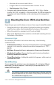
To install the switch into a 19-inch standard chassis: STEP 1 Place one of the supplied brackets on the side of the switch so that the four holes of the brackets align to the screw holes, and then use the four supplied screws to secure it. STEP 2 Repeat the previous step to attach the other bracket to the opposite side of the switch. STEP 3 After the brackets are securely attached, the switch is now ready 400925 to be installed into a standard 19-inch rack.
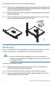
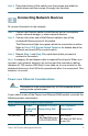
STEP 4 Place the bottom of the switch over the screws and slide the switch down until the screws fit snugly into the slots. 3 Connecting Network Devices To connect the switch to the network: STEP 1 Connect an Ethernet cable to the Ethernet port of a computer, printer, network storage, or other network devices. STEP 2 Connect the other end of the Ethernet cable to one of the numbered Ethernet ports of the switch. The Ethernet port light turns green when the connection is active.
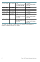
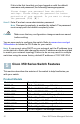
SF350-48MP 740 Watts 802.3af/at 1–48 *60-Watt PoE: ports 60-Watt PoE 802.3af/at, 1,2,3,4,25,26,27,28 4-pair PoE SG350-8PD 124 Watts 1–8 802.3af/at SG350-10P 62 Watts 1–8 802.3af/at SG350-10MP 128 Watts 1–8 802.3af/at SG355-10P 62 Watts 1–8 802.3af/at SG350-28P 195 Watts 1–24 802.3af/at *60-Watt PoE: ports 60-Watt PoE 802.3af/at, 1,2,13,14 4-pair PoE SG350-28MP 382 Watts 1–24 802.3af/at *60-Watt PoE: ports 60-Watt PoE 802.
CAUTION 5 4 Consider the following when connecting switches capable of supplying PoE: The PoE models of the switches are PSE (Power Sourcing Equipment) that are capable of supplying DC power to attaching PD (Powered Devices). These devices include VoIP phones, IP cameras, and wireless access points. The PoE switches can detect and supply power to pre-standard legacy PoE Powered Devices.
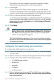
Configuring Your Switch Using the Web-based Interface To access the switch with a web-based interface, you must know the IP address that the switch is using. The switch uses the factory default IP address of 192.168.1.254, with a subnet of /24. When the switch is using the factory default IP address, the System LED flashes continuously.
The default username is cisco. The default password is cisco. Usernames and passwords are both case sensitive. STEP 7 Click Log In. If this is the first time that you have logged on with the default username and password, the Change Password page opens. The rules for constructing a new password are displayed on the page. STEP 8 Enter a new password and confirm the password. NOTE Password complexity is enabled by default.
If this is the first time that you have logged on with the default username and password, the following message appears: Please change your password from the default settings. Please change the password for better protection of your network. Do you want to change the password (Y/N) [Y]? STEP 5 Enter Y, and set a new administrator password. NOTE Password complexity is enabled by default. The password must comply with the default complexity rules.
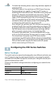
SG350-10MP SG355-10P 10-Port Gigabit PoE Managed Switch 10-Port Gigabit PoE Managed Switch Front Panel The ports, LEDs, and Reset button are located on the front panel of the switch as represented in the following illustrations. SF350-48MP SG350-8PD SG355-10P Front Panel Ports USB Port—The USB port connects the switch to a USB device so that you can save and restore the configuration files, firmware images, and SYSLOG files through the connected USB device.
• Some SFP interfaces are shared with one other RJ-45 port, called a combo port. When the SFP is active, the adjacent RJ-45 port is disabled. • The LEDs of the corresponding RJ-45 port flash green to respond to the SFP interface traffic. Front Panel LEDs PoE (if present)—(Amber) Located on the right of the port. The LED lights steady when power is being supplied to a device attached to the corresponding port.
6 Returning the Switches to the Factory Default Settings To use the Reset button to reboot or reset the switch, do the following: • To reboot the switch, press and hold the Reset button for less than ten seconds. • To restore the switch to its factory default settings: – Disconnect the switch from the network or disable all DHCP servers on your network. – With the power on, press and hold the Reset button for more than ten seconds.
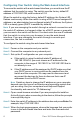
• Replace the power adapter, before replacing the switch, if the situation continues. Bad Ethernet connection • Check the LEDs for proper indications. See Front Panel for details. • Check the connectors of the Ethernet cable to ensure that they are firmly plugged into the switch and your computer. • Use a different Ethernet cable or port. Bad Console port connection • Verify the console cable connectors are firmly plugged into the switch and your computer.
7 Where to Go From Here Cisco Support Community www.cisco.com/go/smallbizsupport Cisco Support and Resources www.cisco.com/go/smallbizhelp Phone Support Contacts www.cisco.com/en/US/support/ tsd_cisco_small_business _support_center_contacts.html Cisco Firmware Downloads www.cisco.com/go/smallbizfirmware Select a link to download firmware for Cisco Products. No login is required.
Americas Headquarters Cisco Systems, Inc. www.cisco.com Cisco has more than 200 offices worldwide. Addresses, phone numbers, and fax numbers are listed on the Cisco website at www.cisco.com/go/offices. Cisco and the Cisco logo are trademarks or registered trademarks of Cisco and/or its affiliates in the U.S. and other countries. To view a list of Cisco trademarks, go to this URL: www.cisco.com/go/trademarks. Third-party trademarks mentioned are the property of their respective owners.