USER GUIDE 48-Port 10/100 + 4-Port Gigabit Switch with WebView and Power over Ethernet Model: SRW248G4P BUSINESS SERIES
Table of Contents About This Guide 1 Icon Descriptions . . . . . . . . . . . . . . . . . . . . . . . . . . . . . . . . . . . . . . . . . . . . . . 1 Online Resources . . . . . . . . . . . . . . . . . . . . . . . . . . . . . . . . . . . . . . . . . . . . . . 1 Copyright and Trademarks . . . . . . . . . . . . . . . . . . . . . . . . . . . . . . . . . . . . . . . .
Table of Contents Port Management > LACP . . . . . . . . . . . . . . . . . . . . . . . . . . . . . . . . . . . . . 19 Port Management > PoE Power Settings . . . . . . . . . . . . . . . . . . . . . . . . . . . . 19 VLAN Management . . . . . . . . . . . . . . . . . . . . . . . . . . . . . . . . . . . . . . . . . . . . 20 VLAN Management > Create VLAN . . . . . . . . . . . . . . . . . .
Table of Contents Multicast > Static Member Ports . . . . . . . . . . . . . . . . . . . . . . . . . . . . . . . . . 43 Multicast > Static Router Ports . . . . . . . . . . . . . . . . . . . . . . . . . . . . . . . . . . 44 Multicast > Member Ports Query . . . . . . . . . . . . . . . . . . . . . . . . . . . . . . . . 44 Multicast > Router Ports Query . . . . . . . . . . . . . . . . . . . . .
About This Guide About This Guide Icon Descriptions While reading through the User Guide you may encounter various icons designed to call attention to a specific item. Below is a description of these icons: NOTE: This checkmark indicates that there is a note of interest and is something that you should pay special attention to while using the product. WARNING: This exclamation point indicates that there is a caution or warning and it is something that could damage your property or product.
Chapter 1 Introduction Chapter 1: Introduction Thank you for choosing the 48-Port 10/100 + 4-Port Gigabit Switch with WebView and Power over Ethernet. This Switch will allow you to network better than ever. The 48-Port 10/100 + 4-Port Gigabit Switch with WebView delivers non-blocking, wire speed switching for your 10 and 100 megabit network clients, plus multiple options for connecting to your network backbone.
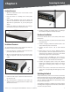
Chapter 2 Chapter 2: Product Overview Front Panel The LEDs and ports are located on the front panel of the Switch. Front Panel POWER (Green/Amber) Lights up green to indicate that power is being supplied to the Switch. Lights amber to indicate that the Switch’s power-on-self-test (POST) is in progress. Blinks amber to indicate that the POST has failed.
Chapter 2 Product Overview MiniGBIC (1-2) The Switch is equipped with two miniGBIC ports that have shared Gigabit Ethernet ports (G3 and G4) which provide for the installation of one expansion module. These ports provide links to high-speed network segments or individual workstations at speeds of up to 1000Mbps (Gigabit Ethernet).
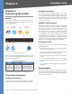
Connecting the Switch Chapter 3 Chapter 3: Connecting the Switch Overview This chapter will explain how to connect network devices to the Switch. The following diagram shows a typical network configuration. Internet Cable./DSL Modem Router Wireless Access Point Full-Duplex Considerations The Switch provides full-duplex support for its RJ-45 ports. Full-duplex operation allows data to be sent and received simultaneously, doubling a port’s potential data throughput.
Chapter 3 Connecting the Switch Desktop Placement • Attach the rubber feet to the recessed areas on the bottom of the Switch. • Place the Switch on a desktop near an AC power source. • Keep enough ventilation space for the switch and check the environmental restrictions mentioned in “Appendix C: Specifications” as you are placing the Switch. • Connect the Switch to network devices according to the Hardware Installation instructions below. Mounting in Rack 5 .
Chapter 4 Configuration Using the Console Interface Chapter 4: Configuration Using the Console Interface 4 . Select a port to communicate with the switch. Select COM1 or COM2. Overview The Switch features a menu-driven console interface for basic switch configuration. You can easily manage your network from the screens through the console port. Before you can use the console interface, you will need to configure the HyperTerminal application. Configuring the HyperTerminal Application 1 .
Chapter 4 Configuration Using the Console Interface Configuring the Switch through the Console Interface System Configuration Menu The Console Interface consist of a series of menus. Each menu has several options, which are listed vertically. A highlight in each menu lets you select the option you wish to choose; pressing the Enter key activates the highlighted option.
Configuration Using the Console Interface Chapter 4 Versions Management Settings The Versions screen displays the Boot Version, Software Version, Loader Version and the Hardware Version. The Management Settings screen displays the Serial Port Configuration. Versions Management Settings Boot Version This file runs when the Switch is turned on. It performs power-on diagnostics and loads the operating system for the Switch. Software Version This file contains the programming code that runs the Switch.
Chapter 4 Configuration Using the Console Interface You can add up to five user accounts in addition to the default admin account. The admin account cannot be deleted from the system. To save the new user account information, use the arrow keys to select Save and press Enter. IP Configuration The IP Configuration screen displays four menu choices: IP Address Settings, HTTP/HTTPS, SNMP, and Network Diagnostics. Management VLAN Set the ID number of the Management VLAN.
Configuration Using the Console Interface Chapter 4 • Startup-config If the file is a configuration file. Destination File Specify where the file is to be transferred. Select one of the following: • TFTP If the file is to be uploaded to a TFTP server. • Image If the file is to be downloaded as a software code file. • Startup-config If the file is a configuration file SNMP SNMP Server Enable or Disable the SNMP function for the Switch.
Chapter 4 Configuration Using the Console Interface Back to Main Menu Select Back to Main Menu if you want to return to the main menu. Port Status The Port Status screen allows you to view the status of a port. The Port, Enable, Link Status, Spd/Dpx, and Flow Control are displayed. Auto-negotiation (Port Capabilities) This option enables or disables auto-negotiation. When auto-negotiation is enabled, you need to specify the capabilities to be advertised.
Chapter 4 Configuration Using the Console Interface System PoE Configuration Port PoE Configuration The Power Configuration screen allows you to set the PoE power allocation from the Switch to connected devices. The Power Port Configuration screen allows you to set the PoE settings for each port. Select the Edit action and use the left-right and up-down arrows to select the attribute you would like to set. You can set the Admin Status, the Priority, and the Power Allocation.
Configuring the Switch Chapter 5 Chapter 5: Configuring the Switch Open your web browser and enter http://192.168.1.254 into the address field. Press the Enter key and the Password screen will appear. Setup > Summary The Setup > Summary screen displays a summary of Switch information. The settings cannot be modified from the Setup > Summary screen. Many of the settings can be modified from the Setup > Network Settings screen. Address Bar NOTE: The default IP address is 192.168.1.254.
Configuring the Switch Chapter 5 System Information Identification Serial Number The serial number of the Switch is displayed. System Name Specifies the name of the Switch. Enter the name into the text field provided. By default, a system name is not defined. Model Name The model name of the Switch is displayed. Hardware version The current hardware version is displayed. Boot Version The current boot version is displayed. Firmware Version The current software version is displayed.
Configuring the Switch Chapter 5 IP Address Address of the VLAN interface that is allowed management access. Valid IP addresses consist of four numbers, 0 to 255, separated by periods. (Default: 192.168.1.254) Set Time Subnet Mask This mask identifies the host address bits used for routing to specific subnets. (Default: 255.255.255.0) Set the system time using Simple Network Time Protocol (SNTP) automatically Sets the system clock automatically using SNTP.
Configuring the Switch Chapter 5 Port Management Flow Control Indicates the type of flow control currently in use (IEEE 802.3x, Back-Pressure, or None). Port functionality can be controlled using the Port Management settings. Speeds, duplex, grouping, and Power over Ethernet settings, and more can be defined. Type Indicates the port type ((100Base-TX, 1000Base-T, or SFP).
Chapter 5 The following capabilities are supported. • 10half Supports 10 Mbps half-duplex operation • 10full Supports 10 Mbps full-duplex operation • 100half Supports 100 Mbps half-duplex operation • 100full Supports 100 Mbps full-duplex operation Configuring the Switch LAG Displays the LAG number. Description Displays the description assigned to the interface. Administrative Status Indicates whether the interface is enabled or disabled.
Configuring the Switch Chapter 5 Description Allows you to describe an interface. Flow Control Click the checkbox to enable flow control. Autonegotiation Click autonegotiation. the checkbox to enable Set the System Priority, Port Priority and LACP Timeout for the Port Actor After you have completed setting the port LACP parameters, click Save Settings.
Chapter 5 VLAN Management Configuring the Switch VLAN Management > Port Settings A VLAN is a group of ports that can be located anywhere in the network, but communicate as though they belong to the same physical segment. VLANs help to simplify network management by allowing you to move devices to a new VLAN without having to change any physical connections.
Configuring the Switch Chapter 5 Ingress filtering Determines how to process frames tagged for VLANs for which the ingress port is not a member. (Default: Disabled) Ingress filtering only affects tagged frames. If ingress filtering is disabled and a port receives frames tagged for VLANs for which it is not a member, these frames will be flooded to all other ports (except for those VLANs explicitly forbidden on this port).
Chapter 5 Mode Indicates the VLAN switch port mode for the interface. Join VLAN Configures the selected interface to be a member of other VLANs. VLANs VLANs for which the selected interface is a member. Configuring the Switch Statistics > RMON History The RMON History screen allows you to monitor your network for common errors and overall traffic rates.
Chapter 5 Statistics > RMON Alarms The RMON Alarms screen allows you to record important events and critical network problems. The RMON Alarm and Event Control Tables are used together to define specific criteria that will generate response events. Alarms can be set to test data over any specified time interval and can monitor absolute or changing values, such as a statistical counter reaching a specific value, or a statistic changing by a certain amount over a set interval.
Configuring the Switch Chapter 5 Event Description A text comment that describes the entry in the Event Setting Table. Statistics > 802.1x Statistics Type The type of action that is taken for an alarm. This can be None, Log, Trap, or Log and Trap. Community The SNMP community name that a trap manager must use to receive trap messages. Owner The name of the person who created this entry in the Event Setting Table. (Maximum 127 characters). Click on the Add button to add an Event index entry to the table.
Chapter 5 ACL > IP based ACL Configuring the Switch Wildcard Mask Enter the Wildcard Mask for the Source/ Destination IP addresses. Match CoS Packet priority settings based on the following criteria: • DSCP DSCP priority level. (Range: 0-63) • Precedence IP precedence level. (Range: 0-7) Then click the Add to List Button To remove an ACL rule, select an ACL rule from the table and click Remove. When all rules are removed from the ACL the ACL is also removed.
Configuring the Switch Chapter 5 Ethernet Type Specify an Ethernet Type. This option can only be used to filter Ethernet II formatted packets. (Range: 0-65535) A detailed listing of Ethernet protocol types can be found in RFC 1060. A few of the more common types include 0800 (IP), 0806 (ARP), 8137 (IPX). Security > Authentication Servers Then click the Add to List button. To remove an ACL rule, select an ACL rule from the table and click Remove.
Configuring the Switch Chapter 5 TACACS Server Setting The Switch provides Terminal Access Controller Access Control System (TACACS+) client support. TACACS+ provides centralized security for validation of users accessing the device. TACACS+ provides a centralized user management system, while still retaining consistency with RADIUS and other authentication processes. The TACACS+ protocol ensures network integrity through encrypted protocol exchanges between the device and TACACS+ server.
Chapter 5 Operation Mode Allows single or multiple hosts (clients) to connect to an 802.1X-authorized port. (Options: SingleHost, Multi-Host; Default: Single-Host) Maximum Count (1-1024) The maximum number of hosts that can connect to a port when the Multi-Host operation mode is selected. The default value is 5. Mode Sets the authentication mode to one of the following options: • Auto Requires a dot1x-aware client to be authorized by the authentication server.
Chapter 5 To use port security, specify a maximum number of addresses to allow on the port and then let the Switch dynamically learn the pair for frames received on the port. When the port has reached the maximum number of MAC addresses the selected port will stop learning. The MAC addresses already in the address table will be retained and will not age out. Any other device that attempts to use the port will be prevented from accessing the Switch.
Chapter 5 Security > SSH Settings Configuring the Switch SSH Server-Key Size (512-896) Specifies the SSH server key size. The server key is a private key that is never shared outside the Switch. The host key is shared with the SSH client, and is fixed at 1024 bits. (Default:768) Security > SSH Host-Key Settings Security > SSH Settings The Secure Shell (SSH) includes server/client applications that can provide remote management access to the Switch and act as a secure replacement for Telnet.
Configuring the Switch Chapter 5 Generate This button is used to generate the host key pair. Note that you must first generate the host key pair before you can enable the SSH server. Clear This button clears the host key from both volatile memory (RAM) and non-volatile memory (Flash). QoS Network traffic is usually unpredictable, and the only basic assurance that can be offered is best effort traffic delivery. To overcome this challenge, Quality of Service (QoS) is applied throughout the network.
Configuring the Switch Chapter 5 Port to CoS Queue Settings Modify the default priority for any interface using the text field provided. You can set the Switch to service the queues based on a strict rule that requires all traffic in a higher priority queue to be processed before lower priority queues are serviced, or use Weighted Round-Robin (WRR) queuing that specifies a relative weight of each queue.
Configuring the Switch Chapter 5 The Switch supports a common method of prioritizing layer 3/4 traffic to meet application requirements. Traffic priorities can be specified in the IP header of a frame using the priority bits in the Type of Service (ToS) octet. If priority bits are used, the ToS octet may contain six bits for Differentiated Services Code Point (DSCP) service.
Chapter 5 Configuring the Switch Select the entry from the table that you wish to change, then click Edit Class Element. Add rules to a selected class using the ACL list drop-down menu or the IP DSCP, IP Precedence and VLAN text fields provided, then click Add.
Configuring the Switch Chapter 5 • Exceed Action Specifies whether the traffic that exceeds the specified rate or burst will be dropped or the DSCP service level will be reduced. • Set Decreases DSCP priority for out of conformance traffic. (Range: 0-63). Rate limiting can be applied to individual ports or LAGs. When an interface is configured with this feature, the traffic rate will be monitored by the hardware to verify conformity.
Chapter 5 Spanning Tree > STP Status Configuring the Switch Root Maximum Age The maximum time (in seconds) a device can wait without receiving a configuration message before attempting to reconfigure. All device ports (except for designated ports) should receive configuration messages at regular intervals. Any port that ages out STA information (provided in the last configuration message) becomes the designated port for the attached LAN.
Configuring the Switch Chapter 5 Spanning Tree Type Specifies the type of spanning tree used on the Switch: • STP Spanning Tree Protocol (IEEE 802.1D); i.e., when this option is selected, the Switch will use RSTP set to STP forced compatibility mode). • RSTP Rapid Spanning Tree Protocol (IEEE 802.1w). RSTP is the default. • MSTP Multiple Spanning Tree Protocol (IEEE 802.1s).
Configuring the Switch Chapter 5 The Port Information displays the current status of the ports in the Spanning Tree. Port Displays the port number. State Shows if Spanning Tree has been enabled on this interface. To enable STP on a port click the state checkbox for that port then click Save Settings to save the changes. Status Displays current state of this port within the Spanning Tree: • Discarding Port receives STA configuration messages, but does not forward packets.
Configuring the Switch Chapter 5 Priority Defines the priority used for this port in the Spanning Tree Protocol. If the path cost for all ports on a switch are the same, the port with the highest priority (i.e., lowest value) will be configured as an active link in the Spanning Tree. This makes a port with higher priority less likely to be blocked if the Spanning Tree Protocol is detecting network loops.
Chapter 5 Activate Protocol Migration Test If at any time the switch detects STP BPDUs, including Configuration or Topology Change Notification BPDUs, it will automatically set the selected interface to forced STP-compatible mode. However, you can also use the Protocol Migration button to manually re-check the appropriate BPDU format (RSTP or STP-compatible) to send on the selected interfaces. (Default: Disabled) Administrative Link Type The link type attached to this interface.
Configuring the Switch Chapter 5 VLAN ID VLAN to assign to this selected MST instance. (Range: 1-4093) Instance ID Instance identifier of this spanning tree. (Default: 0) Included VLANs VLANs assigned this instance. Bridge Priority The priority of a spanning tree instance.
Configuring the Switch Chapter 5 Interface Priority Defines the priority used for this port in the Spanning Tree Protocol. If the path cost for all ports on a switch are the same, the port with the highest priority (i.e., lowest value) will be configured as an active link in the Spanning Tree. This makes a port with higher priority less likely to be blocked if the Spanning Tree Protocol is detecting network loops.
Chapter 5 Multicast > Global Settings Configuring the Switch Multicast > Static Member Ports Multicast > Global Settings You can configure the Switch to forward multicast traffic intelligently. Based on the IGMP query and report messages, the Switch forwards traffic only to the ports that request multicast traffic. This prevents the Switch from broadcasting the traffic to all ports and possibly disrupting network performance.
Configuring the Switch Chapter 5 Multicast > Static Router Ports You can use the Member Ports Query screen to display the ports on the Switch attached to a neighboring multicast router/switch for each VLAN and multicast IP address. Select a VLAN ID and the IP address for a multicast service from the drop-down menus. The Switch will display all the interfaces that are propagating this multicast service.
Chapter 5 The switch can be configured to accept management commands from Simple Network Management Protocol (SNMP) applications. You can configure the switch to respond to SNMP requests or generate SNMP traps. When SNMP management stations send requests to the switch (either to return information or to set a parameter), the switch provides the requested data or sets the specified parameter.
Configuring the Switch Chapter 5 SNMP > Views SNMP > Group Profile SNMP > Views SNMP > Group Profile View Name The name of the SNMP view. Click the View Name option and then select a view from the drop-down menu. Group Name The name of the SNMP group to which the user is assigned. (Range: 1-32 characters). New View Name Create a new SNMP view by clicking the New View Name option and entering a view name into the field.
Configuring the Switch Chapter 5 SNMP > Group Membership Data Privacy Privacy Protocol The encryption algorithm use for data privacy; only 56-bit DES is currently available. Privacy Password A minimum of eight plain text characters is required. SNMP > Communities You may configure up to five community strings authorized for management access by clients using SNMP v1 and v2c. All community strings used for IP Trap Managers should be listed in this table.
Configuring the Switch Chapter 5 SNMP > Notification Recipient UDP Port Specifies the UDP port number used by the trap manager. Timeout The number of seconds to wait for an acknowledgment before resending an inform message. (Range: 0-2147483647 centiseconds; Default: 1500 centiseconds) Retry times The maximum number of times to resend an inform message if the recipient does not acknowledge receipt. (Range: 0-255; Default: 3) Admin The Admin tab provides access to system administration settings and tools.
Configuring the Switch Chapter 5 Admin > Forwarding Database Static Address Setting A static address can be assigned to a specific interface on the Switch. Static addresses are bound to the assigned interface and will not be moved. When a static address is seen on another interface, the address will be ignored and will not be written to the address table. Static Address Counts The number of manually configured addresses. The Switch allows 1000 Static Address Counts.
Configuring the Switch Chapter 5 Admin > Log System Logging The Switch allows you to configure and limit system messages that are logged to flash or RAM memory, configure the logging of messages that are sent to remote System Log (Syslog) servers, and set an event-level threshold for sending e-mail alert messages to system administrators. The system allows you to enable or disable event logging, and specify which event levels are logged to RAM or flash memory.
Chapter 5 Logging Trap Limits log messages that are sent to the remote Syslog server for all levels up to the specified level. For example, if level 3 is specified, all messages from level 0 to level 3 will be sent to the remote server. (Range: 0-7, Default: 7) Syslog Server Displays the list of remote server IP addresses that will receive Syslog messages. The maximum number of host IP addresses allowed is five.
Configuring the Switch Chapter 5 Admin > Cable Test The following are some commonly displayed results of a ping: • Normal response The normal response occurs in one to ten seconds, depending on network traffic. • Destination does not respond If the host does not respond, a “timeout” appears in ten seconds. • Destination unreachable The gateway for this destination indicates that the destination is unreachable. • Network or host unreachable The gateway found no corresponding entry in the route table.
Chapter 5 Admin > Jumbo Frame Configuring the Switch Admin > Firmware Upgrade Admin > Jumbo Frame Admin > Firmware Upgrade The Switch provides more efficient throughput for large sequential data transfers by supporting jumbo frames up to 10240 bytes on the Gigabit ports and mini jumbo frames on the 10/100Mbps ports. Compared to standard Ethernet frames that run only up to 1.5 KB, using jumbo frames significantly reduces the per-packet overhead required to process protocol encapsulation fields.
Chapter 5 Configuring the Switch Enter the file name of the software or use the Browse button to locate the file on the PC, then click Save Settings. Admin > Reboot Restarts the Switch retaining the current configuration settings. Admin > Reboot Click the Reboot button, then click OK to confirm. Admin > Factory Default Restores the Switch’s factory default settings. Admin > Factory Default Click the Reset to Factory Default Configuration button, then click OK to confirm and restart the Switch.
Appendix A About Gigabit Ethernet and Fiber Optic Cabling Appendix A: About Gigabit Ethernet and Fiber Optic Cabling Gigabit Ethernet Gigabit Ethernet runs at speeds of 1Gbps (Gigabit per second), ten times faster than 100Mbps Fast Ethernet, but it still integrates seamlessly with 100Mbps Fast Ethernet hardware. Users can connect Gigabit Ethernet hardware with either fiber optic cabling or copper Category 5e cabling, with fiber optics more suited for network backbones.
Glossary Appendix B Appendix B: Glossary Baud - Indicates the number of signaling elements transmitted each second. This glossary contains some basic networking terms you may come across when using this product. Bit - A binary digit. WEB: For additional terms, please visit the glossary at www.linksys.com/glossary Access Mode - Specifies the method by which user access is granted to the system.
Appendix B CoS (Class of Service) - The 802.1p priority scheme. CoS provides a method for tagging packets with priority information. A CoS value between 0-7 is added to the Layer II header of packets, where zero is the lowest priority and seven is the highest. DDNS (Dynamic Domain Name System) - Allows the hosting of a website, FTP server, or e-mail server with a fixed domain name (e.g., www.xyz.com) and a dynamic IP address.
Appendix B Glossary MAC (Media Access Control) Address - The unique address that a manufacturer assigns to each networking device. RADIUS (Remote Authentication Dial-In User Service) - A protocol that uses an authentication server to control network access. Mask - A filter that includes or excludes certain values, for example parts of an IP address. RJ-45 (Registered Jack-45) - An Ethernet connector that holds up to eight wires.
Appendix B Glossary TCP (Transmission Control Protocol) - A network protocol for transmitting data that requires acknowledgement from the recipient of data sent. TCP/IP (Transmission Control Protocol/Internet Protocol) - A set of instructions PCs use to communicate over a network. Telnet - A user command and TCP/IP protocol used for accessing remote PCs. TFTP (Trivial File Transfer Protocol) - A version of the TCP/IP FTP protocol that has no directory or password capability.
Specifications Appendix C Appendix C: Specifications Specifications Other Management Model SRW248G4P Ports 48 RJ-45 connectors for 10BASE-T and100BASE-TX 4 RJ-45 connectors for 10BASE-T, 100BASE-TX and 1000BASE-T 2 Shared SFP slots Cabling Type UTP CAT 5 or better for 10BASE-T/100BASE-TX, UTP CAT 5e or better for 1000BASE-T LEDs Power, Link/Act, Speed Performance Switching Capacity 17.6 Gbps, non-blocking MAC table size 8K Number of VLANs 256 Security Features IEEE 802.1X 802.
Appendix C Specifications QoS Priority levels 4 Hardware queues Scheduling Priority Queueing and Weighted Round Robin (WRR) Class of Service Port-based 802.1p VLAN priority based IPv4 IP precedence/ToS/DSCP TCP/UDP port Layer 2 VLAN Port-based and 802.1q based VLANs Management VLAN HOL Blocking Head of line blocking prevention Jumbo frame Supports frames up to 10K byte frames Standards 802.3 10BASE-T Ethernet, 802.3u 100BASE-TX Fast Ethernet, 802.3ab 1000BASE-T Gigabit Ethernet, 802.
Appendix D Appendix D: Warranty and Regulatory Information Limited Warranty Linksys warrants to You that, for a period of five years (the “Warranty Period”), your Linksys Product will be substantially free of defects in materials and workmanship under normal use. Your exclusive remedy and Linksys’ entire liability under this warranty will be for Linksys at its option to repair or replace the Product or refund Your purchase price less any rebates. This limited warranty extends only to the original purchaser.
Appendix D Warranty and Regulatory Information FCC Statement Règlement d’Industry Canada This product has been tested and complies with the specifications for a Class B digital device, pursuant to Part 15 of the FCC Rules. These limits are designed to provide reasonable protection against harmful interference in a residential installation.
Appendix D User Information for Consumer Products Covered by EU Directive 2002/96/EC on Waste Electric and Electronic Equipment (WEEE) This document contains important information for users with regards to the proper disposal and recycling of Linksys products.
Appendix D Warranty and Regulatory Information Español (Spanish) - Información medioambiental para clientes de la Unión Europea Italiano (Italian) - Informazioni relative all’ambiente per i clienti residenti nell’Unione Europea La Directiva 2002/96/CE de la UE exige que los equipos que La direttiva europea 2002/96/EC richiede che le lleven este símbolo en el propio aparato y/o en su embalaje no deben eliminarse junto con otros residuos urbanos no seleccionados.
Appendix D Malti (Maltese) - Informazzjoni Ambjentali għal Klijenti fl-Unjoni Ewropea Id-Direttiva Ewropea 2002/96/KE titlob li t-tagħmir li jkun fih is-simbolu fuq il-prodott u/jew fuq l-ippakkjar ma jistax jintrema ma’ skart muniċipali li ma ġiex isseparat. Is-simbolu jindika li dan il-prodott għandu jintrema separatament minn ma’ l-iskart domestiku regolari.
Appendix D Warranty and Regulatory Information Slovenčina (Slovak) - Informácie o ochrane životného prostredia pre zákazníkov v Európskej únii Svenska (Swedish) - Miljöinformation för kunder i Europeiska unionen Podľa európskej smernice 2002/96/ES zariadenie s týmto Det europeiska direktivet 2002/96/EC kräver att utrustning symbolom na produkte a/alebo jeho balení nesmie byť likvidované spolu s netriedeným komunálnym odpadom.
Appendix E Contact Information Appendix E: Contact Information Linksys Contact Information Website http://www.linksys.com E-Mail support@linksys.com FTP Site ftp.linksys.com Advice Line 800-546-5797 (LINKSYS) Support 800-326-7114 RMA (Return Merchandise 949-823-3000 Authorization) Fax 949-823-3002 NOTE: Details on warranty and RMA issues can be found in the Warranty and Regulatory Information section of this Guide.