2 CHAPT ER Installing a LightStream 2020 Switch Installing a LightStream 2020 multiservice ATM switch (LS2020 switch) in a networking environment involves several tasks in two major categories: • Installing the LS2020 Hardware Separate sections in this chapter are devoted to the following topics: — “Observing Safety Precautions” — “Unpacking and Inspecting LS2020 Hardware” — “Installing an LS2020 Switch in Rack” — “Wiring a DC-Powered System” — “Installing Fantails” — “Attaching Data Cables” — “Closing
Observing Safety Precautions Observing Safety Precautions Warning LS2020 switches are designed and manufactured to meet accepted safety standards. However, improper use can result in electrical shock, fire hazards, and personal injury. Read the following instructions carefully before installing and using an LS2020 switch. Heed all Cautions and Warnings. Electrostatic Discharge Protection Static electricity can damage or degrade electronic components.
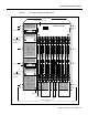
Installing an LS2020 Switch in Rack Installing an LS2020 Switch in Rack This section explains how to mount an LS2020 chassis in an equipment rack. Note For physical stability, when an LS2020 chassis is installed in a rack, the equipment configuration should comply with UL Standard 1950, Par. 4.1.1, and IEC 950, 4.1.1. Cooling Air and Hardware Placement An LS2020 chassis takes in cooling air at the bottom of the front panel and exhausts it at the top rear and right side of the chassis.
Installing an LS2020 Switch in Rack If your system is fully configured with function cards, you may also remove some or all of these cards to further reduce the weight of the chassis. (Refer to the LightStream 2020 Hardware Reference and Troubleshooting Guide for component removal instructions.) Put all removed electronic components in antistatic shielding bags or place them on antistatic mats. Note Do not remove disk assemblies as a means of reducing chassis weight.
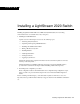
Installing an LS2020 Switch in Rack Figure 2-1 Front View of LightStream 2020 Chassis Mounting flanges Blower (behind cover) LightStream 2020 ™ Disk assembly Disk assembly handle unsafe for lifting! Disk assembly H4812 Disk assembly handle unsafe for lifting! ESD jack NP card Line cards Switch cards Line cards Slots for mounting screws (12 places) Installing a LightStream 2020 Switch 2-5
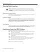
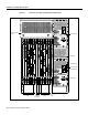
Installing an LS2020 Switch in Rack Figure 2-2 Rear View of AC-powered LightStream 2020 Chassis Blower (behind cover) AC power tray R F CEMAC RX O O A TX0 R F 1 RX1 O A TX1 O R F 2 RX2 TX RX O A RX 1 TX R F O A RX 2 TX TX Warnhinweise fur den Gebrauch des Lasers sind im Installationshandbuch enthalten. R F O A RX TX RX R F E3AC 1 3 5 7 RX0 TX R F FEAC 0 2 4 6 O A Consulter le manuel d'installation au sujet de l'avertissement sur le laser.
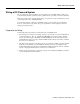
Wiring a DC-Powered System Wiring a DC-Powered System The procedure in this section explains how to wire a DC-powered LS2020 switch to a DC power source. This task should be performed only by qualified service personnel or a licensed electrician. This section applies only to systems with the DC power option. If you have a standard AC-powered system, skip to the section “Installing Fantails.
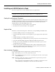
Wiring a DC-Powered System Figure 2-3 Connections to DC-powered Chassis Terminal block for alarm circuit Removable cover Terminal block for system power H3690 Circuit breaker/ power switch Wiring Procedure Warning The wiring task should be performed only by a licensed electrician or qualified service personnel. Untrained personnel may be exposed to hazardous DC voltages.
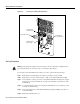
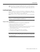
Installing Fantails Step 7 Repeat the procedure above if the LS2020 switch contains a second DC power tray. Step 8 Observe the green power LED on the front of the power tray when power is applied. If the LED is not lit, check for incorrectly connected wires or problems in the DC power source. Installing Fantails This section explains how to mount and connect fantails in your LS2020 switch (see Figure 2-4). Fantails provide connectors for data cables on low-speed (V.35, X.
Installing Fantails Figure 2-4 Fantail Cable Connections Low-speed access card V.35 fantail Front view H3691 Rear view RS-449 fantail Rear view 100-pin high-density connectors support four ports each Front view Fantail Installation Procedure To install fantails in your LS2020 switch, perform the following steps: Note Before installing fantails, check the interface jumpers on each low-speed access card. These jumpers must be set to the interface displayed on the fantail(s) for that card.
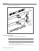
Attaching Data Cables Step 3 Attach the fantail cable(s) to the back of the fantail and the corresponding access card in the chassis. (Performing this task now is recommended, rather than installing the fantail first and having to reach behind it to attach the cable(s) to a connector that you cannot observe directly.) Note that the cable is reversible; that is, either end of the cable can be connected to the fantail. Exercise care to avoid suspending the weight of the fantail on the cable.
Closing the Chassis Note For ease of maintenance, route cables at the back of the LS2020 chassis in a way that enables you to later remove any access card without disconnecting cables attached to other access cards or fantails. Closing the Chassis Before applying system power, check the front and back of the system to ensure that all boards, disks, blowers, bulkheads, filler panels, and covers are in place and secured firmly to the chassis frame.
Applying System Power Figure 2-5 LightStream 2020 AC and DC Power Trays Power switch Terminal block Power inlet Power switch Power switch Terminal block Chassis with DC power trays H3671 Power switch Power inlet Chassis with AC power trays Note When the LS2020 switch is powered up, the blowers start running and the test and control system (TCS) applies power to the cards and initiates the power-on self test (POST) sequence.
Installing Modems Figure 2-6 LightStream 2020 Power-up Sequence Green LED on power supply lights up TCS powers up; LEDs on each card light up TCS slaves enable power on cards; VCC LEDs light up to indicate local power on each card Blowers start running Switch cards arbitrate ~5 seconds to select master POST executes; yellow FLT LED lights up; green RDY LEDs blink on each card while POST runs POST passes ? Yellow FLT LED lights up; green RDY LED goes out Yellow FLT LED goes out; green RDY LED ligh
Basic LS2020 Configuration Tasks • • • Zoom 9624V Zoom FXV (FXV9624V) Hayes SmartModem 2400 V.24 For information on the default modem port settings and how to change them, see the LightStream 2020 Network Operations Guide. Basic LS2020 Configuration Tasks This section explains how to enter basic configuration information for your LS2020 chassis in order to make it operable in your networking environment and manageable from your NMS.
Basic LS2020 Configuration Tasks Host Name You must assign a unique host name to each LS2020 node. Typically, a name can be chosen to reflect the node’s geographic location (for example, Tokyo2) or its function within an organization (for example, mfg3). The name may consist of any combination of letters and numbers up to 32 characters, but it must not begin with a number. Thus, Pensacola23 is a valid host name, but 23Pensacola is not; similarly, Pensacola.
Basic LS2020 Configuration Tasks • Subnet mask for the NP’s Ethernet address The subnet mask for the NP’s Ethernet address specifies which portion of the IP address is the network number and which portion is the host ID. This mask is the same for all nodes on the Ethernet LAN attached to the primary NP. You can obtain the subnet mask from the Ethernet LAN administrator.
Basic LS2020 Configuration Tasks — For an E3 trunk port, specify the cable length (0 – 400 feet, 300 – 1000 feet, 800 – 1300 feet, or 1100 – 1900 feet) and the cell payload scrambling mode (enabled or disabled). — For an OC-3c trunk port, specify the clocking mode (internal or external). For more information about trunk port configuration, refer to the LightStream 2020 Configuration Guide.
Basic LS2020 Configuration Tasks Setting Console/Modem Baud Rates through TCS Hub Commands To detect and set baud rates for the console and modem ports for Release 2 switch cards, you use the TCS hub show and set commands, respectively. These commands interpret and manipulate the contents of specific fields in the midplane EEPROM used for storing initialized baud rates for the console and modem ports.
Basic LS2020 Configuration Tasks 2400 1200 4800 38400 300 Note The console port baud rate can be changed at any time, but the change will take effect only on power-up of the LS2020 chassis or a reset of the applicable switch card. Similarly, the modem port baud rate can be changed at any time, but the change will take effect only on power-up of the LS2020 chassis, a reset of the applicable switch card, or when the modem port is reinitialized via the TCS hub init command.
Basic LS2020 Configuration Tasks Step 2 Issue the set command at the TCS hub prompt, as shown below: set {sa | sb} modem baudrate {2400 | 9600} In this command, specify the switch card having the non-matching baud rate. For example, if you have dialed into the LS2020 chassis through switch card A, specify sb in the set command; if you have dialed into the chassis through switch card B, specify sa in the set command. Finally, specify the desired baud rate for the modem port.
Basic LS2020 Configuration Tasks When the system verifies itself as being responsive (through the return of an appropriate prompt), you can then make the terminal fully operational in your LS2020 environment by connecting it to the NP. To do so, proceed directly to the section below entitled “Connecting the Terminal to the NP.
Basic LS2020 Configuration Tasks Proceed to the section below entitled “Connecting the Terminal to the NP.” Step 10 For baud rate selection, this step requires that your LS2020 chassis be equipped with two switch cards. It also assumes that you can communicate with the switch card that currently needs no baud rate adjustment. Dial into this card via its modem port or use the terminal attached to its console port to set the baud rate, as instructed in Step 11 below.
Basic LS2020 Configuration Tasks Special Consideration: Running Scripts Separately When you enter configuration data, two scripts are invoked automatically that prompt you for basic configuration information (see bullets below). If you err in entering information in response to script prompts, you can run the scripts again separately. To do so, enter the name of the script you want to run at the bash# (root) prompt or the single-user ($) prompt.
Basic LS2020 Configuration Tasks **** LynxOS is down **** ***booting: drive:0, partition:0, kernel:”lynx.os”, flags:0x4308 Resetting SCSI bus Kernel linked for 0xea010000 LOAD AT 0x10000 471040+40960+136260[61824+50608] TOTAL SIZE: 745080 at 0x1001c START AT 0x10020 NP memory size: 32 MB ILACC: EEPROM enet addr:8:0:8:0:14:25, Silicon Rev:0x5, IB:0xea146620 virtual console: IB: 0xea139d20 NCR 53C710: Chip Revision: 0x2, IB: 0xec13d000 LynxOS/68040-MVME167 Version 2.1.
Basic LS2020 Configuration Tasks Set the daylight savings method to one of the following values: 0 (no daylight savings) 1 (USA) 2 (Australia) 3 (East Europe) 4 (Central Europe) 5 (Western Europe) Daylight savings method: 1 Set the timezone by specifying the number of minutes west of Greenwich Examples: 300 (US Eastern Time) 360 (US Central Time) 420 (US Mountain Time) 480 (US Pacific Time) Minutes west of Greenwich, England: 300 At the prompt, enter a new date or press to continue.
Basic LS2020 Configuration Tasks Note For an LS2020 switch with two NPs, you must perform this procedure twice—once for each NP. You must enter identical information for each NP. Do not reverse the active and secondary IP addresses on the second NP; these addresses are assigned to the entire chassis, not to individual NPs. If you do not enter the same information for both NPs, your LS2020 switch will not work.
Basic LS2020 Configuration Tasks Network Processor Default IP Router: 197.110.175.2 Chassis configuration contains 1 network processor. Network processor’s on-board Ethernet LAN interface is attached to an external Ethernet LAN. Is the chassis and network processor information correct? (Y/N)? [Y] Y If you confirm that the configuration data you have entered in this step is correct by responding Y to this query, the script continues with the trunk port configuration query below.
Basic LS2020 Configuration Tasks Network Processor Ethernet IP Mask [a.b.c.d]: 255.255.255.0 Is there an IP router on the attached Ethernet LAN (Y/N)? [N] Y Configure the Default IP router for the network processors’ Ethernet LAN interface. Network Processor Ethernet Default IP Router [a.b.c.d]: 197.112.23.1 CHASSIS INFORMATION Host Name: Chassis Primary (Active) IP Address: Chassis Secondary IP Address: Chassis Subnet Mask: LightStream1 192.1.1.11 192.1.1.12 255.255.255.
Basic LS2020 Configuration Tasks 1) Low Speed 2) T3 3) E3 4) OC3 Specify the trunk card type (1-4): 1 Specify the trunk card slot number (1-10): 3 Specify the port number (0-7): 0 DCE/DTE Type: 1) DCE 2) DTE Specify the DCE/DTE type (1-2): 1 DCE Bit Rate: 1) 128 Kb 2) 192 Kb 3) 256 Kb 4) 384 Kb 5) 6) 7) 8) 448 512 768 896 Kb Kb Kb Kb 9) 10) 11) 12) 1344 1536 1792 2688 Kb Kb Kb Kb 13) 3584 Kb 14) 4000 Kb 15) 5376 Kb Specify the DCE Bit Rate (1-15): 1 TRUNK INFORMATION Type: Low Speed Trunk DCE/DTE T
Basic LS2020 Configuration Tasks Line Card ls2020:5 (MS-TR) up. Next, log in to the system and start the CLI using the oper or npadmin account, as shown in the example below: user name: npadmin password: Return When you log into the oper or npadmin account, the CLI starts automatically, first presenting the CLI banner on the console and then the CLI prompt, as shown in the example below: cli: (ls_main) compiled Jul 26 1995 @ 03:45:21 Copyright 1995. Cisco Systems, Inc. All Rights Reserved.
Basic LS2020 Configuration Tasks If the current EEPROMs or the midplane are replaced, you will need to enter the chassis ID and modem information into the EEPROMs on the new midplane. See the LightStream 2020 Hardware Reference & Troubleshooting Guide for instructions on finding the chassis ID and modem information. You are also advised to record any unusual LS2020 behavior. The maintenance log can be highly useful in identifying and correcting chronic or intermittent LS2020 operational problems.
Basic LS2020 Configuration Tasks If Your PC Has Two 1.44-MB Floppy Disk Drives To back up each LS2020 software distribution diskette, perform the following steps: Step 1 Insert the first distribution (source) diskette in floppy disk drive A. Step 2 Insert a blank, formatted (destination) diskette in drive B. Step 3 At the DOS prompt, enter the following command: C:\> diskcopy a: b: /v Step 4 DOS then copies the data from drive A to the backup diskette in drive B.
Basic LS2020 Configuration Tasks 2-34 LightStream 2020 Installation Guide