
user manual

19-16
Catalyst 3750-X and 3560-X Switch Software Configuration Guide
OL-21521-01
Chapter 19 Configuring IEEE 802.1Q and Layer 2 Protocol Tunneling
Configuring Layer 2 Protocol Tunneling
Configuring the Customer Switch
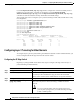
After configuring the SP edge switch, begin in privileged EXEC mode and follow these steps to
configure a customer switch for Layer 2 protocol tunneling for EtherChannels:
Use the no swi
tchport mode trunk, the no udld enable, and the no channel group
channel-group-number mode desirable interface configuration commands to return the interface to the
default settings.
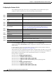
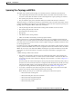
For EtherChannels, you need to configure both the
SP edge switches and the customer switches for
Layer 2 protocol tunneling. (See Figure 19-6 on page 19-10.)
This example shows how to configure the SP edge switch 1 and edge switch 2. VLANs 17, 18, 19, and 20
are the
access VLANs, Fast Ethernet interfaces 1 and 2 are point-to-point tunnel ports with PAgP and
UDLD enabled, the drop threshold is 1000, and Fast Ethernet interface 3 is a trunk port.
SP edge switch 1 configuration:
Switch(config)# interface gigabitethernet1/0/1
Switch(config-if)# switchport acc
ess vlan 17
Switch(config-if)# switchport mod
e dot1q-tunnel
Switch(config-if)# l2protocol-tun
nel point-to-point pagp
Switch(config-if)# l2protocol-tun
nel point-to-point udld
Switch(config-if)# l2protocol-tun
nel drop-threshold point-to-point pagp 1000
Switch(config-if)# exit
Switch(config)# interface gigabit
ethernet1/0/2
Switch(config-if)# switchport acc
ess vlan 18
Switch(config-if)# switchport mod
e dot1q-tunnel
Switch(config-if)# l2protocol-tun
nel point-to-point pagp
Switch(config-if)# l2protocol-tun
nel point-to-point udld
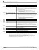
Command Purpose
Step 1
configure terminal Enter global configuration mode.
Step 2
interface interface-id Enter the interface configuration mode. This should be the customer switch
port.
Step 3
switchport trunk encapsulation
dot1q
Set the trunking encapsulation format to IEEE 802.1Q.
Step 4
switchport mode trunk Enable trunking on the interface.
Step 5
udld enable Enable UDLD in normal mode on the interface.
Step 6
channel-group channel-group-number
mode desirable
Assign the interface to a channel group, and specify desirable for the PAgP
mode. For more information about configuring EtherChannels, see
Chapter 40, “Configuring EtherChannels and Link-State Tracking.”
Step 7
exit Return to global configuration mode.
Step 8
interface port-channel port-channel
number
Enter port-channel interface mode.
Step 9
shutdown Shut down the interface.
Step 10
no shutdown Enable the interface.
Step 11
end Return to privileged EXEC mode.
Step 12
show l2protocol Display the Layer 2 tunnel ports on the switch, including the protocols
configured, the thresholds, and the counters.
Step 13
copy running-config startup-config (Optional) Save your entries in the configuration file.