
user manual

21-12
Catalyst 3750-X and 3560-X Switch Software Configuration Guide
OL-21521-01
Chapter 21 Configuring MSTP
Understanding RSTP
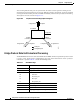
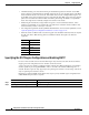
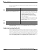
After ensuring that all of the ports are synchronized, the switch sends an agreement message to the
designated switch corresponding to its root port. When the switches connected by a point-to-point link
are in agreement about their port roles, the RSTP immediately transitions the port states to forwarding.
The sequence of events is shown in Figure 21-5.
Figure 21-5 Sequence of Events During Rapid Convergence
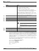
Bridge Protocol Data Unit Format and Processing
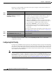
The RSTP BPDU format is the same as the IEEE 802.1D BPDU format except that the protocol version
is set to 2. A new 1-byte Version 1 Length field is set to zero, which means that no version 1 protocol
information is present. Table 21-3 shows the RSTP flag fields.
2. Block
9. Forward
1. Proposal4. Agreement
6. Proposal
Root port
Designated port
8. Agreement 10. Agreement
Edge port
7. Proposal
5. Forward
3. Block
11. Forward
88761
Ta ble 21-3 RSTP BPDU Flags
Bit Function
0 Topology change (TC)
1 Proposal
2–3:
00
01
10
11
Port role:
Unknown
Alternate port
Root port
Designated port
4 Learning
5 Forwarding
6 Agreement
7 Topology change acknowledgement (TCA)