
user manual

39-14
Catalyst 3750-X and 3560-X Switch Software Configuration Guide
OL-21521-01
Chapter 39 Configuring QoS
Understanding QoS
Queueing and Scheduling Overview
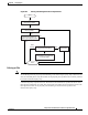
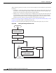
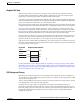
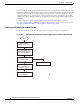
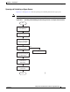
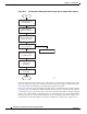
The switch has queues at specific points to help prevent congestion as shown in Figure 39-6 and
Figure 39-7.
Figure 39-6 Ingress and Egress Queue Location on Catalyst 3750-X Switches
Figure 39-7 Ingress and Egress Queue Location on Catalyst 3560-X Switches
Because the total inbound bandwidth of all ports can exceed the bandwidth of the stack or internal ring,
ingress queues are located after the packet is classified, policed, and marked and before packets are
forwarded into the switch fabric. Because multiple ingress ports can simultaneously send packets to an
egress port and cause congestion, outbound queues are located after the stack or internal ring.
MarkerPolicer
MarkerPolicer
Marker
Ingress
queues
Stack ring
Egress
queues
Policer
MarkerPolicer
Classify
Traffic
SRRSRR
86691
MarkerPolicer
MarkerPolicer
Marker
Ingress
queues
Internal
ring
Egress
queues
Policer
MarkerPolicer
Classify
Traffic
SRRSRR
90563