S e n d d o c u m e n t a t i o n c o m m e n t s t o m d s f e e d b a ck - d o c @ c i s c o . c o m . C H A P T E R 35 Configuring iSCSI Cisco MDS 9000 Family IP storage (IPS) services extend the reach of Fibre Channel SANs by using open-standard, IP-based technology. The switch allows IP hosts to access Fibre Channel storage using the iSCSI protocol. Note The iSCSI feature is specific to the IPS module and is available in Cisco MDS 9200 Switches or Cisco MDS 9500 Directors.
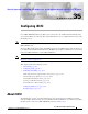
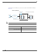
Chapter 35 Configuring iSCSI About iSCSI Figure 35-1 Transporting iSCSI Requests and Responses for Transparent iSCSI Routing iscsi Intelligent storage array Switch 1 IP host A Fibre Channel SAN IP network A C Transporting iSCSI requests and responses over an IP network Transporting FCP requests and responses between a Cisco MDS switch and a storage array 91567 B Routing SCSI requests and responses (Through the IPS module) Each iSCSI host that requires access to storage through the IPS module
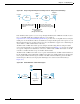
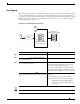
Chapter 35 Configuring iSCSI Configuring iSCSI Fibre Channel SAN View—iSCSHI Host as an HBA MDS IP Network iSCSI host A Fibre Channel SAN FC Target T-3 120872 Virtual FC host A Figure 35-4 iSCSI to FCP (Fibre Channel) Routing MDS iSCSI to FCP(FC) routing FC Session IP host A IP Network iqn.host A iSCSI iSCSI Virtual Target iqn.
Chapter 35 Configuring iSCSI Configuring iSCSI • • • • Presenting iSCSI Hosts as Virtual Fibre Channel Hosts, page 35-10 iSCSI Access Control, page 35-19 iSCSI Session Authentication, page 35-22 iSCSI Immediate Data and Unsolicited Data Features, page 35-25 iSCSI Interface Advanced Features, page 35-26 Displaying iSCSI Information, page 35-29 Enabling iSCSI To use the iSCSI feature, you must explicitly enable iSCSI on the required switches in the fabric.
Chapter 35 Configuring iSCSI Configuring iSCSI Presenting Fibre Channel Targets as iSCSI Targets • Dynamic mapping—automatically maps all the Fibre Channel target devices/ports as iSCSI devices. Use this mapping to create automatic iSCSI target names. • Static mapping—Manually create iSCSI target devices and map them to the whole Fibre Channel target port or a subset of Fibre Channel LUNs. With this mapping, you must specify unique iSCSI target names.
iqn.1987-05.com.cisco:05..01-01.3100112233445566 (see Figure 35-5). Dynamic Target Mapping MDS-mgntIP Virtual iSCSI Target IP Network iSCSI 1/1 iqn.host A LUN0 LUN0 LUN1 LUN1 LUN2 LUN2 iqn.1987-05.com.cisco:05..01-01.3100112233445566 iscsi import target fc 35-6 120780 IP host A iSCSI pwwn 31.00.11.22.33.44.55.
Static Mapping You can manually (statically) create an iSCSI target by assigning a user-defined unique iSCSI node name to it. The iSCSI qualified name is restricted to a minimum length of 16 characters and a maximum of 223 characters. A statically mapped iSCSI target can either map the whole Fibre Channel target port (all LUNs in the target port mapped to the iSCSI target), or it can contain one or more LUs from a Fibre Channel target port (see Figure 35-1).
Chapter 35 Configuring iSCSI Configuring iSCSI Note Advertising Static iSCSI Targets Command Step 1 Purpose switch(config-iscsi-tgt)# interface GigabitEthernet 2/5 no advertise interface GigabitEthernet 2/5 iSCSI Virtual Target Configuration Examples Example 1 Figure 35-7 Assigning iSCSI Node Names pWWN 28:00:01:02:03:04:05:06 Example 2 Cisco MDS 9000 Family Configuration Guide 35-8 OL-6973-03, Cisco MDS SAN-OS Release 2.
Figure 35-8 Mapping LUNs to a iSCSI Node Name iSCSI view of storage device iqn.1987-02.com.cisco.target-1 Fibre Channel storage device 0 0 iqn.1987-02.com.cisco.target-2 1 2 pWWN 28:00:01:02:03:04:05:06 0 112190 0 iqn.1987-02.com.cisco.target-3 Example 3 Figure 35-9 Mapping LUNs to Multiple iSCSI Node Names iSCSI view of storage device iqn.1987-02.com.cisco.target-1 Fibre Channel storage device 0 0 iqn.1987-02.com.cisco.target-2 1 2 3 pWWN 28:00:01:02:03:04:05:06 0 1 iqn.1987-02.com.
Presenting iSCSI Hosts as Virtual Fibre Channel Hosts Initiator Identification • • Command Step 1 Step 2 Step 3 35-10 Purpose
Chapter 35 Configuring iSCSI Configuring iSCSI Initiator Presentation Modes • to Fibre Channel, each host can have different zoning or LUN access control on the Fibre Channel storage device. • In proxy-initiator mode, there is only one virtual Fibre Channel host per one IPS port and all iSCSI hosts use that to access Fibre Channel targets.
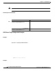
Chapter 35 Configuring iSCSI Configuring iSCSI Figure 35-10 Virtual Host HBA Port MDS host A iSCSI Virtual FC host A host B iSCSI IP Network host C Virtual FC host B Target T-1 Virtual FC host C 120876 iSCSI • • • SCSI_FCP in the FC-4 type field of the name server Initiator flag in the FC-4 feature of the name server Vendor-specific iSCSI GW flag in the FC-4 type field to identify the N-port device as a iSCSI gateway device in the NS.
Chapter 35 Configuring iSCSI Configuring iSCSI iSCSI Initiator Idle Timeout WWN Assignment for iSCSI Initiators An iSCSI host is mapped to an N port’s WWNs by one of the following mechanisms: • Dynamic mapping (default) • Static mapping Dynamic Mapping The WWNs are allocated from the MDS switch's WWN pool. The WWN mapping to the iSCSI host is maintained as long as the iSCSI host has at least one iSCSI session to the IPS port.
name Command Purpose Step 1 Step 2 iqn.1987-02.com.cisco.initiator no iscsi initiator name iqn.1987-02.com.cisco.initiator ip-address config terminal iscsi initiator ip-address 10.50.0.0 no iscsi initiator ip-address 10.50.0.
Command Purpose Step 1 Step 2s Step 3 Returns to EXEC mode. Step 4 Checking for WWN Conflicts install all Command Step 1 Step 1 iscsi duplicate-wwn-check List of Potential WWN Conflicts: -------------------------------Node : iqn.
Multiplexing IPS Ports MDS Host A iSCSI Proxy initiator host Host B iSCSI IP network iSCSI switch# switch(config)# switch(config)# switch(config-if)# 120874 Host C
Command Purpose Step 3 Step 4 VSAN Membership for iSCSI • • VSAN Membership for iSCSI Hosts Command Purpose Step 1 Step 2 Step 3 Note
Chapter 35 Configuring iSCSI Configuring iSCSI Note VSAN Membership for iSCSI Interfaces Tip no iscsi interface vsan-membership Command Purpose Step 1 Step 2 Step 3 Step 4 Example of VSAN membership for iSCSI devices • • • Cisco MDS 9000 Family Configuration Guide OL-6973-03, Cisco MDS SAN-OS Release 2.
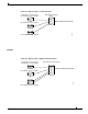
Chapter 35 Configuring iSCSI Configuring iSCSI MDS Host A (VSAN X) VSAN X iSCSI Virtual Host A VSAN X Host B iSCSI T1 IP network VSAN Y Host C iSCSI interface 1/1 port VSAN = Y VSAN Y Virtual Host B Virtual Host C T2 120870 iSCSI Advanced VSAN membership for iSCSI hosts iSCSI Access Control • • Fibre Channel Zoning Based Access Control devices. Zoning is the standard access control mechanism for Fibre Channel devices which is applied within the context of a VSAN.
Chapter 35 Configuring iSCSI Configuring iSCSI Common mechanisms of identifying members in Fibre Channel Zone are the following (see Chapter 19, “Configuring and Managing Zones” for details of Fibre Channel Zoning): • Fibre Channel device pWWN • Interface and Switch WWN. Device connecting via that interface is within the zone: In the case of iSCSI, behind an iSCSI interface multiple iSCSI devices may be connected.
iSCSI ACL Based Access Control • • • Note Command Step 1 Step 2 Step 3 Step 4 Purpose
Chapter 35 Configuring iSCSI Configuring iSCSI Enforcing Access Control • • its login is rejected. If the iSCSI host is allowed, it validates if the virtual Fibre Channel N port used by the iSCSI host and the Fibre Channel target mapped to the static iSCSI virtual target are in the same Fibre Channel zone.
To configure AAA authentication for an iSCSI user, follow these steps: Enters configuration mode. iscsi default group RadServerGrp aaa authentication iscsi default group TacServerGrp aaa authentication iscsi default local You can configure iSCSI CHAP or None authentication at both the global level and at each interface level. The authentication for a Gigabit Ethernet interface or subinterface overrides the authentication method configured at the global level.
Command Purpose Step 1 Step 2 Restricting iSCSI Initiator Authentication Command Purpose Step 1 Step 2 Step 3 Tip Mutual CHAP Authentication Command Step 1 Purpose
Chapter 35 Configuring iSCSI Configuring iSCSI Step 2 !@*asdsfsdfjh!@df (!@*asdsfsdfjh!@df) for all initiators. username user1 password 0 abcd12AAA no iscsi authentication username testuser Configures the switch user account (user1) along with a password (abcd12AAA) specified in clear text (indicated by 0—default) for all initiators. The password is limited to 64 characters. Removes the global configuration for all initiators. Enters configuration mode. config t iscsi initiator name iqn.1987-02.
These two features help reduce I/O time for small write commands because it removes one round-trip between the initiator and the target for the R2T PDU. As an iSCSI target, the MDS switch allows up to 64 KB of unsolicited data per command. This is controlled by the FirstBurstLength parameter during iSCSI login negotiation phase. If an iSCSI initiator supports immediate data and unsolicited data features, these features are automatically enabled on the MDS switch with no configuration required.
QoS Configure the differentiated services code point (DSCP) value of 3 to be applied to all outgoing IP packets in this iSCSI interface. The valid range for the iSCSI DSCP value is from 0 to 63. Reverts the switch to its factory default (marks all packets with DSCP value 0). iSCSI Routing Modes Each mode negotiates different operational parameters, has different advantages and disadvantages, and is suitable for different usages.
Figure 35-13 compares the messages exchanged by the iSCSI routing modes.
Chapter 35 Configuring iSCSI Configuring iSCSI switch(config-if)# switch(config-if)# Displaying iSCSI Information Displaying iSCSI Interfaces Example 35-1 Displays the iSCSI Interface Information iscsi4/1 is up Hardware is GigabitEthernet Port WWN is 20:cf:00:0c:85:90:3e:80 Admin port mode is ISCSI Port mode is ISCSI Speed is 1 Gbps iSCSI initiator is identified by name Number of iSCSI session: 0 (discovery session: 0) Number of TCP connection: 0 Configured TCP parameters Local Port is 3260 PMTU disc
Data-in 0 pdus, 0 bytes switch# iscsi2/1 5 minutes input rate 704 bits/sec, 88 bytes/sec, 1 frames/sec 5 minutes output rate 704 bits/sec, 88 bytes/sec, 1 frames/sec iSCSI statistics 974756 packets input, 142671620 bytes Command 2352 pdus, Data-out 44198 pdus, 92364800 bytes, 0 fragments, unsolicited 0 bytes show iscsi stats iscsi 2/1 detail FCP Forward:
Xfer_rdy:1804 (Rcvd:1804) Data-In:90453 (Rcvd:90463), 92458248 bytes Response:2352 (Rcvd:2362), with sense 266 TMF Resp:0 Login:attempt:13039, succeed:110, fail:12918, authen fail:0 Rcvd:NOP-Out:914582, Sent:NOP-In:914582 NOP-In:0, Sent:NOP-Out:0 TMF-REQ:0, Sent:TMF-RESP:0 Text-REQ:18, Sent:Text-RESP:27 Bad header digest:0 Sent:PLOGI:10, Rcvd:PLOGI_ACC:10, PLOGI_RJT:0 PRLI:10, Rcvd:PRLI_ACC:10, PRLI_RJT:0, Error:0, From initiator:0 LOGO:4, Rcvd:LOGO_ACC:0, LOGO_RJT:0 PRLO:4, Rcvd:PRLO_ACC:0, PRLO_RJT:0 AB
<----------------------------Proxy initiator is enabled nWWN is 28:00:00:05:30:00:a7:a1 (system-assigned)<----System-assigned nWWN pWWN is 28:01:00:05:30:00:a7:a1 (system-assigned)<---- System-assigned pWWN show interface iscsi 4/2 nWWN is 11:11:11:11:11:11:11:11 (manually-configured)<----User-assigned nWWN pWWN is 22:22:22:22:22:22:22:22 (manually-configured)<----User-assigned pWWN
Displaying Global iSCSI Information Displays the Current Global iSCSI Configuration and State Example 35-7 Displays Brief Information of All iSCSI Sessions Target VT1 VSAN 1, ISID 00023d000046, Status active, no reservation Session #3 Target VT2 VSAN 1, ISID 00023d000048, Status active, no reservation Initiator 10.10.100.199 Initiator name iqn.1987-05.com.cisco.01.
switch# show iscsi session initiator 10.10.100.199 target VT1 show iscsi session initiator 10.10.100.199 target VT1 detail DataSeqInOrder No, InitialR2T Yes, ImmediateData No Registered LUN 0, Mapped LUN 0 Stats: PDU: Command: 38, Response: 38 Bytes: TX: 8712, RX: 0 Number of connection: 1 Connection #1 Local IP address: 10.10.100.200, Peer IP address: 10.10.100.
iSCSI Node name is 10.10.100.199 iSCSI Initiator name: iqn.1987-05.com.cisco.01.7e3183ae458a94b1cd6bc168cba09d2e iSCSI alias name: oasis-qa Node WWN is 22:03:00:05:30:00:10:e1 (configured) Member of vsans: 1, 5 Number of Virtual n_ports: 1 Virtual Port WWN is 22:00:00:05:30:00:10:e1 (configured) Interface iSCSI 4/1, Portal group tag: 0x180 VSAN ID 5, FCID 0x640000 VSAN ID 1, FCID 0x6c0203 switch# iSCSI Node name is iqn.1987-05.com.cisco:02.3021b0f2fda0.avanti12-w2k Initiator ip addr (s): 10.10.100.
switch# VSAN 1: -------------------------------------------------------------------------FCID TYPE PWWN (VENDOR) FC4-TYPE:FEATURE -------------------------------------------------------------------------0x020101 N 22:04:00:05:30:00:35:e1 (Cisco) scsi-fcp:init isc..w 0x020102 N 22:02:00:05:30:00:35:e1 (Cisco) scsi-fcp:init isc..w 0x0205d4 NL 21:00:00:04:cf:da:fe:c6 (Seagate) scsi-fcp:target 0x0205d5 NL 21:00:00:04:cf:e6:e4:4b (Seagate) scsi-fcp:target ...
====================================================================== -----------------------VSAN:2 FCID:0xef0001 -----------------------port-wwn (vendor) :22:02:00:05:30:00:35:e1 (Cisco) node-wwn :22:01:00:05:30:00:35:e1 class :2,3 node-ip-addr :10.2.2.11 ipa :ff ff ff ff ff ff ff ff fc4-types:fc4_features:scsi-fcp:init iscsi-gw symbolic-port-name : symbolic-node-name :iqn.1987-05.com.cisco.01.14ac33ba567f986f174723b5f9f2377 port-type :N port-ip-addr :0.0.0.
iSCSI High Availability Displaying iSCSI Virtual Targets * Port WWN 21:00:00:20:37:62:c0:0c Configured node all initiator permit is enabled target: VT2 Port WWN 21:00:00:04:cf:4c:52:c1 Configured node all initiator permit is disabled target: iqn.1987-05.com.cisco:05.switch.04-01.
Chapter 35 Configuring iSCSI iSCSI High Availability iSCSI High Availability with Host Running Multi-Path Software MDS Switch IP Network IP 10.1.1.1/24 iSCSI IP 20.1.1.1/24 1/1 2/1 21.1.1.1/24 MDS 1 Ethernet switch 10.1.1.2/24 Storage P1 P2 Logical View Session 1 iqn.com.cisco.mds-1.1-1.P1 H1 Session 2 iSCSI iqn.com.cisco.mds1.1-1.P2 iSCSI P1 IP Network H2 Session 3 P2 iqn.com.cisco.mdsiSCSI 1.1-1.
Chapter 35 Configuring iSCSI iSCSI High Availability iSCSI HA with Host Not Having Any Multi-Path Software • • iSCSI host iSCSI Switch 1 Fibre Channel storage pWWN 1 IP Network pWWN 2 FC 26:00:01:02:03:04:05:06 26:00:01:02:03:10:11:12 Primary access = pWWN1 Secondary access = pWWN 2 ABC 91568 Fibre Channel storage Tip Command Purpose Step 1 Step 2 Cisco MDS 9000 Family Configuration Guide OL-6973-03, Cisco MDS SAN-OS Release 2.
Chapter 35 Configuring iSCSI iSCSI High Availability Command Purpose Step 3 Note Step 4 Step 5 Storage Port Failover LUN Trespass Cisco MDS 9000 Family Configuration Guide OL-6973-03, Cisco MDS SAN-OS Release 2.
Chapter 35 Configuring iSCSI iSCSI High Availability pWWN a1:94:cc fcid 0x550002 Primary IP network IP Addr 10.1.1.1 iqn.initiator.abc Command FC Secondary IP Addr 10.1.1.2 iqn.virtual-target.abc pWWN a1:97:ac fcid 0610003 105219 iSCSI Purpose Step 1 Step 2 Step 3 Step 4 Multiple IPS Ports Connected to the Same IP Network Cisco MDS 9000 Family Configuration Guide OL-6973-03, Cisco MDS SAN-OS Release 2.
Chapter 35 Configuring iSCSI iSCSI High Availability Multiple Gigabit Ethernet Interfaces in the Same IP Network Physical view (iSCSI) IP network IP-10.1.10.100 FC iSCSI HBA FC fabric Logical view IP-10.1.10.100 IP network Network portal 10.1.10.100 IP-10.1.1.1 iqn.host-1 pWWN-P1 FC lqn.com.cisco.mds.5-3.gw.p1 IP-10.1.1.1 FC lqn.com.cisco.mds.2-1.gw.p1 Cisco MDS 9000 Family Configuration Guide OL-6973-03, Cisco MDS SAN-OS Release 2.x 90861 HBA iqn.host-1 Network portal 10.1.1.
Chapter 35 Configuring iSCSI iSCSI High Availability VRRP-Based High Availability Physical view (iSCSI) VRRP across two ports IP network FC iSCSI HBA Virtual IP-10.1.1.1 HBA Network portal 10.1.1.1 Logical view iSCSI FC fabric Virtual IP-10.1.1.1 iqn.host-1 pWWN-P1 FC lqn.com.cisco.mds.vr1.gw.p1 IP network iqn.host-1 FC 90862 lqn.com.cisco.mds.vr1.gw.p1 Cisco MDS 9000 Family Configuration Guide OL-6973-03, Cisco MDS SAN-OS Release 2.
Chapter 35 Configuring iSCSI iSCSI Authentication Setup Guidelines and Scenarios Ethernet PortChannel-Based High Availability Note Ethernet PortChannel iSCSI HBA iqn.host-2 FC fabric FC IP network pWWN-P2 IP-10.1.1.1 iSCSI pWWN-P1 Note iSCSI Authentication Setup Guidelines and Scenarios • • • Note Cisco MDS 9000 Family Configuration Guide OL-6973-03, Cisco MDS SAN-OS Release 2.x 90863 HBA iqn.
Chapter 35 Configuring iSCSI iSCSI Authentication Setup Guidelines and Scenarios No Authentication CHAP with Local Password Database Step 1 Step 2 Step 3 Note Step 4 CHAP with External RADIUS Server Step 1 Step 2 Step 3 Step 4 Step 5 Cisco MDS 9000 Family Configuration Guide OL-6973-03, Cisco MDS SAN-OS Release 2.
Chapter 35 Configuring iSCSI iSCSI Authentication Setup Guidelines and Scenarios Step 6 <---------------- Verify CHAP Step 7 Step 1 Step 2 Step 3 iSCSI Transparent Mode Initiator • • • • • Cisco MDS 9000 Family Configuration Guide OL-6973-03, Cisco MDS SAN-OS Release 2.
Chapter 35 Configuring iSCSI iSCSI Authentication Setup Guidelines and Scenarios • Interface fc 2/1 21:00:00:20:37:6f:fd:97 7/1 Host 1 10.11.1.10 o.01.255891611111 10.15.1.10 01.25589167F74C iSCSI-zone-1 Switch 1 iSCSI Interface fc 2/5 21:00:00:20:37:6f:fe:54 iSCSI iSCSI-zone-2 Host 2 Interface fc 2/9 21:00:00:20:37:a6:a6:5d 94136 7/5 Step 1 Step 2 Step 3 Note Step 4 Step 5 Cisco MDS 9000 Family Configuration Guide OL-6973-03, Cisco MDS SAN-OS Release 2.
Chapter 35 Configuring iSCSI iSCSI Authentication Setup Guidelines and Scenarios Step 6 Note Step 7 Step 8 iscsi-zone-1 Step 9 iscsi-zone-2 Step 10 Step 11 Cisco MDS 9000 Family Configuration Guide OL-6973-03, Cisco MDS SAN-OS Release 2.
Chapter 35 Configuring iSCSI iSCSI Authentication Setup Guidelines and Scenarios Step 12 Note <-----------Target <--------------------------------- iSCSI host (host 1, not online) * fcid 0x6d0001 [pwwn 21:00:00:20:37:6f:fd:97] <------------Target <------------Target <-iSCSI host (host 2, not online) detail Cisco MDS 9000 Family Configuration Guide OL-6973-03, Cisco MDS SAN-OS Release 2.
<--------- <------------------------ Host 2: Initiator ID based on node name because the initiator is entering iSCSI interface 7/5 Host 1: Initiator ID based on IP address because the initiator is entering iSCSI interface 7/1 FCID resolved for host 1 <------------- <------------------------- FCID for host 2
<---------------------<------ <-------------------- <-----<--------------------- IP address of the iSCSI host iSCSI gateway node iSCSI initiator ID is based on the registered node name iSCSI gateway node iSCSI initiator ID is based on the IP address registered in symbolic-node-name field
Target Storage Device Requiring LUN Mapping • • • • Interface fc 2/1 21:00:00:20:37:6f:fd:97 Host 1 iSCSI VSAN 1 Switch 1 iSCSI Interface fc 2/5 21:00:00:20:37:6f:fe:54 iSCSI VSAN 2 Host 2 94137 Interface fc 2/9 21:00:00:20:37:a6:a6:5d Step 1 Step 2 Step 3 Step 4
Chapter 35 Configuring iSCSI iSCSI Authentication Setup Guidelines and Scenarios Step 5 Step 6 Step 7 <-----Host 2 <-----------------------------------Host 1 Note Step 8 Note Step 9 Step 10 Note • • show iscsi initiator Cisco MDS 9000 Family Configuration Guide OL-6973-03, Cisco MDS SAN-OS Release 2.
Chapter 35 Configuring iSCSI iSCSI Authentication Setup Guidelines and Scenarios Step 11 Note Step 12 Zoneset activation initiated. check zone status switch# zoneset name iscsi-zoneset-v2 vsan 2 zone name iscsi-zone-2 vsan 2 * fcid 0x750001 [pwwn 21:00:00:20:37:6f:fe:54] * fcid 0x750101 [pwwn 21:00:00:20:37:a6:a6:5d] pwwn 20:06:00:0b:fd:44:68:c2 switch# Initiator iqn.1987-05.com.cisco:01.e41695d16b1a Initiator ip addr (s): 10.11.1.
<--- iSCSI initiator in name server <----- iSCSI initiator in name server
<-- Session to first target Session to <-- second target <------------------------ Dynamic WWN as static WWN not assigned <--------- Static pWWN for the initiator vsan membership <-- iSCSI initiator entry in name server
About iSCSI Storage Name Services • • – – –
About iSNS Client Functionality ; a unique entity is associated with each IPS interface The iSNS client uses a registration interval value of 15 minutes. If the client fails to refresh the registration during this interval, the server will deregister the entries.
Creating an iSNS Client Profile Command Purpose Command Purpose Step 1 Step 2 Step 3 Step 1 Step 2 Step 3 isns reregister Verifying iSNS Client Configuration show isns profile
Chapter 35 Configuring iSCSI Creating an iSNS Client Profile show isns profile counters show isns Displays iSNS Queries Cisco MDS 9000 Family Configuration Guide OL-6973-03, Cisco MDS SAN-OS Release 2.
Example 35-22 Displays Tagged iSNS Interfaces ^^^^^^^^^^^^^^^^ 5 minutes input rate 112 bits/sec, 14 bytes/sec, 0 frames/sec 5 minutes output rate 0 bits/sec, 0 bytes/sec, 0 frames/sec 1935 packets input, 132567 bytes 4 multicast frames, 0 compressed 0 input errors, 0 frame, 0 overrun 0 fifo 1 packets output, 42 bytes, 0 underruns 0 output errors, 0 collisions, 0 fifo 0 carrier errors discover
Zone 1 Zone 2 P1 SW-1 SW-2 P2 FC FC Gigabitethernet 2/1 Gigabitethernet 3/1 IP Network - 1 TOE iqn.host1 1. 2. 3. 4. 5. 6. 7. 8. Configuring iSNS Servers iSCSI TOE iqn.
Chapter 35 Configuring iSCSI Configuring iSNS Servers Enabling the iSNS Server Before iSNS server feature can be enabled, iSCSI must be enabled (see the “Enabling iSCSI” section on page 35-4). When you disable iSCSI, iSNS is automatically disabled. When the iSNS server is enabled on a switch, every IPS port whose corresponding iSCSI interface is up is capable of servicing iSNS registration and query requests from external iSNS clients.
Chapter 35 Configuring iSCSI Configuring iSNS Servers iSNS Client Registration and Deregistration Target Discovery DevGetNext DevAttrQuery Cisco MDS 9000 Family Configuration Guide OL-6973-03, Cisco MDS SAN-OS Release 2.
Displays Explicitly Registered Objects SCN Bitmap: OBJ_UPDATED|OBJ ADDED|OBJ REMOVED|TARGET&SELF Node Alias: VSANS: 1(*), 5(*) Portal IP Address: 192.168.100.2 Entity Index: 2 Portal Index: 1 ESI Interval: 0 ESI Port: 4180 TCP Port: 4179 SCN Port: 4180 switch# Entity Id: isns.entity.mds9000 Index: 1 Last accessed: Fri Jul 30 04:08:16 2004 iSCSI Node Name: iqn.com.cisco.
Node Type: Target(1) Node Index: 0x80000002 VSANS: iSCSI Node Name: iqn.com.cisco.disk2 Entity Index: 1 Node Type: Target(1) Node Index: 0x80000003 WWN(s): 22:00:00:20:37:39:dc:45 VSANS: Portal IP Address: 192.168.100.5 Entity Index: 1 Portal Index: 3 Portal IP Address: 192.168.100.6 Entity Index: 1 Portal Index: 5 Entity Id: dp-204 Index: 2 TCP Port: 3205 TCP Port: 3205 Last accessed: Fri Jul 30 04:08:46 2004 iSCSI Node Name: iqn.1991-05.com.
Portal IP Address: 192.168.100.6 Entity Index: 1 Portal Index: 5 TCP Port: 3205 switch# Entity Id: isns.entity.mds9000 Index: 1 Last accessed: Fri Jul 30 04:08:16 2004 iSCSI Node Name: iqn.com.cisco.disk1 Entity Index: 1 Node Type: Target(1) Node Index: 0x80000001 WWN(s): 22:00:00:20:37:39:dc:45 VSANS: iSCSI Node Name: iqn.isns-first-virtual-target Entity Index: 1 Node Type: Target(1) Node Index: 0x80000002 VSANS: iSCSI Node Name: iqn.com.cisco.
switch# iSCSI Node Name: iqn.com.cisco.disk1 Entity Index: 1 Node Type: Target(1) Node Index: 0x80000001 WWN(s): 22:00:00:20:37:39:dc:45 VSANS: 1 switch# iSCSI Node Name: iqn.1987-05.com.cisco:05.switch1.02-03.22000020375a6c8f Entity Index: 1 Node Type: Target(1) Node Index: 0x3000003 Configured Switch WWN: 20:00:00:0d:ec:01:04:40 WWN(s): 22:00:00:20:37:5a:6c:8f VSANS: 1 ... iSCSI Node Name: iqn.com.cisco.
switch# ------------------------------------------------------------------------------IPAddress TCP Port Index SCN Port ESI port ------------------------------------------------------------------------------192.168.100.5 3205 3 192.168.100.6 3205 5 - switch# Portal IP Address: 192.168.100.5 Entity Index: 1 Portal Index: 3 Portal IP Address: 192.168.100.
switch1# ------------------------------------------------------------------------------Entity ID Last Accessed ------------------------------------------------------------------------------dp-204 Tue Sep 7 23:15:42 2004 switch# ------------------------------------------------------------------------------Entity ID Last Accessed ------------------------------------------------------------------------------isns.entity.
switch# iSCSI Global configuration: Switch: 20:00:44:0d:ec:01:02:40 iSCSI Auto Import: Enabled Use the (see Example 35-43). command to display CFS peers switch information about the iSNS application switch# Scope : Physical -------------------------------------------------Switch WWN IP Address -------------------------------------------------20:00:00:00:ec:01:00:40 10.10.100.
Chapter 35 Configuring iSCSI Default Settings Parameters Default CHAP or none authentication mechanism. revert-primary-port Cisco MDS 9000 Family Configuration Guide OL-6973-03, Cisco MDS SAN-OS Release 2.
Chapter 35 Configuring iSCSI Default Settings Cisco MDS 9000 Family Configuration Guide OL-6973-03, Cisco MDS SAN-OS Release 2.