Cisco VG350 Voice Gateway Hardware Installation Guide THE SPECIFICATIONS AND INFORMATION REGARDING THE PRODUCTS IN THIS MANUAL ARE SUBJECT TO CHANGE WITHOUT NOTICE. ALL STATEMENTS, INFORMATION, AND RECOMMENDATIONS IN THIS MANUAL ARE BELIEVED TO BE ACCURATE BUT ARE PRESENTED WITHOUT WARRANTY OF ANY KIND, EXPRESS OR IMPLIED. USERS MUST TAKE FULL RESPONSIBILITY FOR THEIR APPLICATION OF ANY PRODUCTS. Americas Headquarters Cisco Systems, Inc. 170 West Tasman Drive San Jose, CA 95134-1706 USA http://www.cisco.
THE SOFTWARE LICENSE AND LIMITED WARRANTY FOR THE ACCOMPANYING PRODUCT ARE SET FORTH IN THE INFORMATION PACKET THAT SHIPPED WITH THE PRODUCT AND ARE INCORPORATED HEREIN BY THIS REFERENCE. IF YOU ARE UNABLE TO LOCATE THE SOFTWARE LICENSE OR LIMITED WARRANTY, CONTACT YOUR CISCO REPRESENTATIVE FOR A COPY. The following information is for FCC compliance of Class A devices: This equipment has been tested and found to comply with the limits for a Class A digital device, pursuant to part 15 of the FCC rules.
CONTENTS Preface vii Audience -vii Organization -vii Conventions -viii Safety Warnings -ix Warning Definition -ix Related Documentation -xv Cisco.
Contents Installing SM-D-72FXS 2-3 Grounding 2-3 Cables 2-3 Connecting SM-D-72FXS 2-3 Installing SM-D-48FXS-E 2-4 Grounding 2-4 Cables 2-4 Connecting SM-D-48FXS-E 2-4 FXO Fail-Over Bypass Ports 2-5 Cisco SM-D-72FXS Service Module Specifications Physical Description and LEDs 2-6 Cisco SM-D-48FXS-E Service Module Specifications Physical Description and LEDs 2-6 Port Numbering Conventions 2-6 2-6 2-7 Connecting to the Double-Wide High Density Service Module Ports 2-7 Online Insertion and Removal 2-7 I
Contents Maintaining Safety with Electricity 4-2 General Safety Practices 4-4 Safety Tips 4-4 Preventing Electrostatic Discharge Damage Site Log 4-5 4-5 Keeping Track–Checklist 4-6 Installation Checklist 4-6 Mounting Tools and Equipment Unpacking and Inspection CHAPTER 5 Power-On Procedure Troubleshooting A 4-7 Powering On the Cisco VG350 Voice Gateway Checklist for Power-On APPENDIX 4-7 5-1 5-1 5-1 5-3 Cable Specifications and Information A-1 Console and Auxiliary Port Cables and Pinouts A
Preface This preface discusses the audience, organization, and conventions of this publication and describes how to obtain additional documentation. Audience This publication is designed for experienced IT technicians familiar with Cisco products, IOS CLI, and concepts and technologies of networking.
Contents Conventions Table 2 Installation Guide Conventions Convention Description boldface font Commands and keywords. italic font Variables for which you supply values. [ Keywords or arguments that appear within square brackets are optional. ] {x | y | z} A choice of required keywords appears in braces separated by vertical bars. You must select one. screen font Examples of information displayed on the screen. boldface screen font Examples of information you must enter.
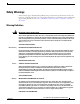
Contents Safety Warnings Safety warnings appear throughout this publication in procedures that, if performed incorrectly, may harm you. A warning symbol precedes each warning statement. To see translations of the warnings that appear in this publication, refer to Cisco VG350 Voice Gateway Regulatory Compliance and Safety Information. Warning Definition Warning IMPORTANT SAFETY INSTRUCTIONS This warning symbol means danger. You are in a situation that could cause bodily injury.
Contents Warnung WICHTIGE SICHERHEITSHINWEISE Dieses Warnsymbol bedeutet Gefahr. Sie befinden sich in einer Situation, die zu Verletzungen führen kann. Machen Sie sich vor der Arbeit mit Geräten mit den Gefahren elektrischer Schaltungen und den üblichen Verfahren zur Vorbeugung vor Unfällen vertraut. Suchen Sie mit der am Ende jeder Warnung angegebenen Anweisungsnummer nach der jeweiligen Übersetzung in den übersetzten Sicherheitshinweisen, die zusammen mit diesem Gerät ausgeliefert wurden.
Contents Varning! VIKTIGA SÄKERHETSANVISNINGAR Denna varningssignal signalerar fara. Du befinner dig i en situation som kan leda till personskada. Innan du utför arbete på någon utrustning måste du vara medveten om farorna med elkretsar och känna till vanliga förfaranden för att förebygga olyckor. Använd det nummer som finns i slutet av varje varning för att hitta dess översättning i de översatta säkerhetsvarningar som medföljer denna anordning.
Contents Aviso INSTRUÇÕES IMPORTANTES DE SEGURANÇA Este símbolo de aviso significa perigo. Você se encontra em uma situação em que há risco de lesões corporais. Antes de trabalhar com qualquer equipamento, esteja ciente dos riscos que envolvem os circuitos elétricos e familiarize-se com as práticas padrão de prevenção de acidentes. Use o número da declaração fornecido ao final de cada aviso para localizar sua tradução nos avisos de segurança traduzidos que acompanham o dispositivo.
Contents Cisco VG350 Voice Gateway Hardware Installation Guide OL-25970-01 xiii
Contents Cisco VG350 Voice Gateway Hardware Installation Guide xiv OL-25970-01
Contents Related Documentation The Cisco IOS software running your Cisco Voice Gateway includes extensive features and functionality. For information that is beyond the scope of this document, or for additional information, use the resources listed in Table 3. Timesaver Table 3 Make sure that you have access to the documents listed in Table 3. See the “Obtaining Documentation” section on page xv for information about obtaining these documents.
Contents Ordering Documentation You can find instructions for ordering documentation at this URL: http://www.cisco.com/univercd/cc/td/doc/es_inpck/pdi.htm You can order Cisco documentation in these ways: • Registered Cisco.com users (Cisco direct customers) can order Cisco product documentation from the Ordering tool: http://www.cisco.com/en/US/partner/ordering/index.shtml • Nonregistered Cisco.
Contents Submitting a Service Request Using the online TAC Service Request Tool is the fastest way to open S3 and S4 service requests. (S3 and S4 service requests are those in which your network is minimally impaired or for which you require product information.) After you describe your situation, the TAC Service Request Tool automatically provides recommended solutions. If your issue is not resolved using the recommended resources, your service request will be assigned to a Cisco TAC engineer.
Contents Obtaining Additional Publications and Information Information about Cisco products, technologies, and network solutions is available from various online and printed sources. • Cisco Marketplace provides a variety of Cisco books, reference guides, and logo merchandise. Visit Cisco Marketplace, the company store, at this URL: http://www.cisco.
CH A P T E R 1 Overview of the Cisco VG350 Voice Gateway This chapter provides a brief description of the Cisco VG350 Voice Gateway (VG) and contains the following sections: • Overview, page 1-1 • VG350 Voice Gateway Chassis, page 1-2 • Interfaces and Service Capabilities, page 1-3 • Physical Description and LEDs, page 1-4 • Software Elements, page 1-9 Overview The Cisco VG350 service module is a high-density analog voice gateway. It is an intermediate path that enables TDM to IP transition.
Chapter 1 Overview of the Cisco VG350 Voice Gateway VG350 Voice Gateway Chassis VG350 Voice Gateway Chassis The following figures show the front and back panels of the VG350 Voice Gateway Chassis: Figure 1-1 • Figure 1-1 shows the Front Panel. • Figure 1-2 shows the Back Panel. Front Panel of the VG350 Voice Gateway 2 3 4 1 344081 1 1 AC OK1 3 ACT status LED 2 SYS status LED 4 PS1 (Right), PS2 (Left) 1. LED goes off if the AC power fails or is disconnected.
Chapter 1 Overview of the Cisco VG350 Voice Gateway Interfaces and Service Capabilities 1 USB serial console port 6 USB0 and USB1 (1, Top) 2 RJ-45 serial console port 7 Ground 3 SFP1 and SFP2 (2, Top) 8 CompactFlash 0 and 1 (0, Far right) 4 10/100/1000 Ethernet ports GE 0/1 and GE 0/2 (GE 0/2,Top) 9 SM-D-72FXS Service Module 5 10/100/1000 Ethernet port GE 0/0 10 SM-D-48FXS-E Service Module Configuration Options The following configuration options are available for Cisco VG350 Voice Gate
Chapter 1 Overview of the Cisco VG350 Voice Gateway Physical Description and LEDs Physical Description and LEDs LED Indicators Table 1-3 describes the LED indicators for the Cisco VG350. Table 1-3 LED Indicators for Cisco VG350 LED Color Description Location on the VG350 PS/PS1 Green System is running. Front bezel Amber System is not running. Green System is running. Amber System is not running. Green AC power connected.
Chapter 1 Overview of the Cisco VG350 Voice Gateway Physical Description and LEDs Table 1-3 LED Indicators for Cisco VG350 (continued) LED Color Description CF0/CF1 Green Flash memory is being accessed; Back panel do not eject the CompactFlash memory card. Amber CompactFlash error. Off Flash memory is not being accessed; okay to eject the CompactFlash memory card. Off No FE or GE link is established. Green PVDM is initialized. Amber PVDM is detected but not initialized.
Chapter 1 Overview of the Cisco VG350 Voice Gateway Physical Description and LEDs Specifications Table 1-4 details the technical specifications of the Cisco VG350 Voice Gateway. Table 1-4 Cisco VG350 Voice Gateway Technical Specifications Description Specification Physical Dimensions (H x W x D) 5.22 x 17.25 x 18.75 in. (88.9 x 438.2 x 476.2 mm), 3 RU height Weight with AC PS 39 lbs (17.69 kg) (without modules) Weight with AC PS 40 lbs (18.
Chapter 1 Overview of the Cisco VG350 Voice Gateway Physical Description and LEDs Table 1-4 Cisco VG350 Voice Gateway Technical Specifications (continued) Description Specification Temperature 23 to 122°F (–5°C to 50°C) (short-term per NEBS/1800m max altitude) Operating altitude maximum 13,123 ft (4000 m) Note For China, the unit cannot operate above 2000 m. The internal AC power supplies do not meet the new Chinese Safety requirements for products that operate in the 2001-5000 m range.
Chapter 1 Overview of the Cisco VG350 Voice Gateway Physical Description and LEDs Table 1-4 Cisco VG350 Voice Gateway Technical Specifications (continued) Description Specification Immunity compliance EMC compliance • CISPR24 ITE-Immunity characteristics, Limits and methods of measurement • EN 55024 ITE-Immunity characteristics, Limits and methods ofmeasurement • EN 50082-1 Electromagnetic compatibility - Generic immunity standard - Part 1 • EN 300-386 Electromagnetic compatibility for TNESD
Chapter 1 Overview of the Cisco VG350 Voice Gateway Software Elements Software Elements The operating system for the Cisco VG350 Voice Gateway is the Cisco IOS software that resides in flash memory. Configuration Connections You can use an ASCII terminal or a PC to configure a Cisco VG350 Voice Gateway.
Chapter 1 Overview of the Cisco VG350 Voice Gateway Software Elements Cisco VG350 Voice Gateway Hardware Installation Guide 1-10 OL-25970-01
CH A P T E R 2 Cisco Double-Wide High Density Analog Service Modules This chapter provides information about the following Double-Wide High Denstiy Analog Service Module (DWSM). Note 1. Cisco SM-D-72FXS Service Module—A 72 FXS port DWSM with 4 out of the 72 ports supporting OPX ‘Lite’ capabilities. 2. Cisco SM-D-48FXS-E Service Module—A 48 FXS port DWSM with all 48 ports supporting OPX Lite capabilities. DWSM refers to both the Cisco SM-D-72FXS and SM-D-48FXS-E Service Module.
Chapter 2 Cisco Double-Wide High Density Analog Service Modules Double-Wide High Density Analog Service Module Overview Double-Wide High Density Analog Service Module Overview The Double-Wide High Density Service Module (DWSM) is supported on the following platforms: • Cisco 3945 • Cisco 3945e • Cisco 3925 • Cisco 3925e • Cisco 2951 The modules can be plugged in the following DWSM slots of the following platforms: • On Cisco 3945 and Cisco 3945e - only on slot 4.
Chapter 2 Cisco Double-Wide High Density Analog Service Modules Double-Wide High Density Analog Service Module Overview Installing SM-D-72FXS Install the SM-D-72FXS according to the instructions in the Installing Cisco Interface Cards in Cisco Access Routers document. Grounding Ensure that the equipment you are working with is properly grounded according to the instructions in the Installing Cisco Interface Cards in Cisco Access Routers document.
Chapter 2 Cisco Double-Wide High Density Analog Service Modules Double-Wide High Density Analog Service Module Overview Installing SM-D-48FXS-E Install the SM-D-72FXS according to the instructions in the Installing Cisco Interface Cards in Cisco Access Routers document. Grounding Ensure that the equipment you are working with is properly grounded according to the instructions in the Installing Cisco Interface Cards in Cisco Access Routers document.
Chapter 2 Cisco Double-Wide High Density Analog Service Modules FXO Fail-Over Bypass Ports FXO Fail-Over Bypass Ports Bypass/Failover Port, also called Fail-over Trunk Bypass, provides a way to use designated analog phone ports to make phone calls through the Public Switch Telephone Network (PSTN) during power-outage or power savings circumstances. Table 2-2 shows the RJ-11 connector assignment.
Chapter 2 Cisco Double-Wide High Density Analog Service Modules Cisco SM-D-72FXS Service Module Specifications Cisco SM-D-72FXS Service Module Specifications Physical Description and LEDs All interface ports and LEDs are on the rear of the chassis. Figure 2-1 illustrates their locations.
Chapter 2 Cisco Double-Wide High Density Analog Service Modules Port Numbering Conventions Port Numbering Conventions Port numbering conventions for the Cisco VG350 Voice Gateway are as follows: • Two Compact Flash slots, CF0 and CF1. • GE ports are 10/100/1000 BASE-T, numbered GE 0/0 through GE 0/2. • 10/100BASE-T ports are numbered 10/100BASE-T 0/0 and 10/100BASE-T 0/1 from right to left.
Chapter 2 Cisco Double-Wide High Density Analog Service Modules EN LED Insertion and Removal Steps This section describes the sequence of steps when inserting or removing a DWSM. OIR can only be done on one service module at a time. It only supports the same service module type. If you remove an SM-D-72FXS, only another SM-D-72FXS can be inserted. Insertion The following steps show how to insert a service module. 1. Insert the service module into the slot. 2.
CH A P T E R 3 Planning Your Installation Before you install your Cisco VG350 Voice Gateway, consider the information in this chapter: • Location and Mounting Requirements, page 3-1 • Distance Limitations for Interface Cables, page 3-4 • Interference Considerations, page 3-5 Location and Mounting Requirements The three mounting possibilities for your Cisco VG350 Voice Gateway are as follows: • Rack-mount • Wall-mount • Bench-top The mounting location must provide the following: • Access to th
Chapter 3 Planning Your Installation Location and Mounting Requirements Enclosed Racks Caution Enclosed racks must have adequate ventilation. An enclosed rack should never be overcrowded and should have louvers and a fan. If the Cisco VG350 Voice Gateway is installed in an enclosed rack with a ventilation fan at the top, make sure that heated air drawn upward from other equipment does not prevent adequate cooling.
Chapter 3 Planning Your Installation Location and Mounting Requirements Power Source A Cisco VG350 Voice Gateway with AC power supply autoselects either 100–127 volt or 200–240 volt operation. AC versions include a 6-foot (1.8-meter) electrical power cord. (A label near the power cord indicates the correct voltage, frequency, current draw, and power dissipation.
Chapter 3 Planning Your Installation Distance Limitations for Interface Cables Cable Types The cable types that are used are dependent on the Cisco VG350 Voice Gateway that you are using. For more information, see the “Interfaces and Service Capabilities” section on page 1-3 and “Cable Specifications and Information” section on page A-1.
Chapter 3 Planning Your Installation Interference Considerations Interference Considerations When you run cables for any significant distance in an electromagnetic field, interference can occur between the electromagnetic field and the signals on the cables. This has two implications for the installation of terminal plant cabling: • Unshielded plant cabling can emit radio interference.
Chapter 3 Planning Your Installation Interference Considerations Cisco VG350 Voice Gateway Hardware Installation Guide 3-6 OL-25970-01
CH A P T E R 4 Installing the Cisco VG350 Voice Gateway This chapter contains the procedures for installing your Cisco VG350 Voice Gateway and consists of the following sections: Tip • Safety Recommendations, page 4-2 • Site Log, page 4-5 • Keeping Track–Checklist, page 4-6 • Mounting Tools and Equipment, page 4-7 • Unpacking and Inspection, page 4-7 While you do this installation, record your progress and site information.
Chapter 4 Installing the Cisco VG350 Voice Gateway Safety Recommendations Safety Recommendations The following information is included to alert you to safety recommendations and best practices when working with this equipment. Maintaining Safety with Electricity Follow these guidelines when working on equipment powered by electricity. Warning High leakage current—earth connection essential before connecting to system power supply.
Chapter 4 Installing the Cisco VG350 Voice Gateway Safety Recommendations Warning This equipment must be grounded. Never defeat the ground conductor or operate the equipment in the absence of a suitably installed ground conductor. Contact the appropriate electrical inspection authority or an electrician if you are uncertain that suitable grounding is available. Statement 1024 Warning This unit might have more than one power supply connection. All connections must be removed to de-energize the unit.
Chapter 4 Installing the Cisco VG350 Voice Gateway Safety Recommendations Warning This equipment contains a ring signal generator (ringer), which is a source of hazardous voltage. Do not touch the RJ-11 (phone) port wires (conductors), the conductors of a cable connected to the RJ-11 port, or the associated circuit-board when the ringer is active. The ringer is activated by an incoming call.
Chapter 4 Installing the Cisco VG350 Voice Gateway Site Log – If possible, send another person to get medical aid. Otherwise, assess the condition of the victim and then call for help. – Determine if the person needs rescue breathing or external cardiac compressions; then take appropriate action. Preventing Electrostatic Discharge Damage Electrostatic discharge (ESD) can damage equipment and impair electrical circuitry.
Chapter 4 Installing the Cisco VG350 Voice Gateway Keeping Track–Checklist Keeping Track–Checklist We recommend that you use an installation checklist and maintain a Site Log. Installation Checklist The Installation Checklist (see Figure 4-1) lists the tasks for installing a Cisco VG350 Voice Gateway. Print a copy of this checklist and mark the entries as you complete each task. For each Cisco VG350 Voice Gateway, include a copy of the checklist in your Site Log.
Chapter 4 Installing the Cisco VG350 Voice Gateway Mounting Tools and Equipment Mounting Tools and Equipment Obtain the following tools and parts to install a Cisco VG350 Voice Gateway: • Standard flat-blade screwdriver as required for attaching brackets to rack or wall • Phillips screwdriver for attaching brackets to a Cisco VG350 Voice Gateway • Mounting brackets and screws for 24-inch rack, if required: – Four telco machine screws, for installing the chassis in a rack (use the screw size required
Chapter 4 Installing the Cisco VG350 Voice Gateway Unpacking and Inspection Cisco VG350 Voice Gateway Hardware Installation Guide 4-8 OL-25970-01
CH A P T E R 5 Powering On the Cisco VG350 Voice Gateway To power on your Cisco VG350 Voice Gateway, perform the following tasks in the order listed, as required: • Checklist for Power-On, page 5-1 • Power-On Procedure, page 5-1 • Troubleshooting, page 5-3 Checklist for Power-On You can power on a Cisco VG350 Voice Gateway if it meets the requirements described in Chapter 4, “Installing the Cisco VG350 Voice Gateway”: • The chassis is securely mounted. • Power cable is connected.
Chapter 5 Powering On the Cisco VG350 Voice Gateway Power-On Procedure To power on the Cisco VG350 Voice Gateway, perform the following: Step 1 Power on your terminal or PC, and configure it for 9600 bps, 8 data bits, 1 stop bit, and no parity. Step 2 Move the Cisco VG350 Voice Gateway power switch to the ON position. The green LED next to the auxiliary port should come on and the fan should operate. If this does not happen, see the “Troubleshooting” section on page 5-3.
Chapter 5 Powering On the Cisco VG350 Voice Gateway Troubleshooting Troubleshooting This section describes possible mechanical problems and corrective actions. Warning Only trained and qualified personnel should be allowed to install, replace, or service this equipment. Statement 1030 Warning No user-serviceable parts inside. Do not open. Statement 1073 If there appears to be a malfunction, first check all cables and connections.
Chapter 5 Powering On the Cisco VG350 Voice Gateway Troubleshooting Cisco VG350 Voice Gateway Hardware Installation Guide 5-4 OL-25970-01
A P P E N D I X A Cable Specifications and Information This appendix provides the connector and pinout information you need for making or purchasing cables used with Cisco VG350 Voice Gateway. To order cables from Cisco, see the “Obtaining Technical Assistance” section on page xvi.
Appendix A Cable Specifications and Information Console and Auxiliary Port Cables and Pinouts Console Port to PC Figure A-1 shows the RJ-45-to-RJ-45 rollover cable assembly and the RJ-45-to-DB-9 female DTE adapter (labeled TERMINAL); Table A-1 lists the pinouts.
Appendix A Cable Specifications and Information Console and Auxiliary Port Cables and Pinouts Console Port to ASCII Terminal Figure A-2 shows the RJ-45-to-RJ-45 rollover cable assembly and the RJ-45-to-DB-25 female DTE adapter (labeled TERMINAL); Table A-2 lists the pinouts.
Appendix A Cable Specifications and Information Console and Auxiliary Port Cables and Pinouts Auxiliary Port to Modem Figure A-3 shows the RJ-45-to-RJ-45 rollover cable assembly and the RJ-45-to-DB-25 male DCE adapter (labeled MODEM); Table A-3 lists the pinouts.
Appendix A Cable Specifications and Information Gigabit Ethernet Port Pinouts (RJ-45) Gigabit Ethernet Port Pinouts (RJ-45) Figure A-4 shows the RJ-45 connector wiring for the Gigabit Ethernet cable; Figure A-4 lists the pinouts. Note Pinout shown is for category 3, 4, or 5 10/100BASE-T connection to an Gigabit Ethernet switch. Figure A-4 8 H11421 1 RJ-45 Connector Wiring Table A-5 Gigabit Ethernet Port Pinouts (RJ-45) Pin1 Signal 1 TX+ 2 TX– 3 RX+ 4 – 5 – 6 RX– 7 – 8 – 1.
Appendix A Cable Specifications and Information Analog Voice Multiport Pinouts (RJ-21X/CA21A) Analog Voice Multiport Pinouts (RJ-21X/CA21A) Figure A-5 shows the RJ-21 connector wiring for the cable used for the multiport analog voice interface. Figure A-5 RJ-21 Connector Wiring 25 26 50 36484 1 RJ-21 cable RJ-21 connector Table A-6 lists the pinouts for the RJ-21 connector.
Appendix A Cable Specifications and Information Analog Voice Multiport Pinouts (RJ-21X/CA21A) Table A-6 RJ-21 Connector Pinouts (continued) Port Number Connector Pin Number Signal Port Number Connector Pin Number Signal 12 12 37 Ring Tip 24 24 49 Ring Tip — — — — 25, 50, 51, 52 GND Cisco VG350 Voice Gateway Hardware Installation Guide OL-25970-01 A-7