Fourth Generation Versatile Interface Processor (VIP4) Installation and Configuration Guide Product Numbers: VIP4-50=, VIP4-80=, MEM-VIP4-64M-SD=, MEM-VIP4-128M-SD=, MEM-VIP4-256M-SD= Introduction This guide provides instructions for installing, configuring, and maintaining the fourth-generation Versatile Interface Processor (VIP4).
Contents Contents This guide includes the following sections: • Related Documentation, page 2 • VIP4 Overview, page 3 • Installation Prerequisites, page 9 • Agency Approvals, page 11 • Safety Guidelines, page 12 • VIP4 Installation Procedures, page 15 • Checking the VIP4 Installation, page 21 • VIP4 Maintenance Procedures, page 28 • VIP4 Troubleshooting, page 40 • Obtaining Documentation, page 40 • Obtaining Technical Assistance, page 41 Related Documentation Your router and the Cisco
VIP4 Overview • Port adapters/interface processors/service adapters: For port adapter information and maintenance information, refer to the specific port adapter installation and configuration guide. See the port adapter index online at http://www.cisco.com/univercd/cc/td/doc/product/core/cis7505/portadpt/index.htm.
VIP4 Overview Using the show diag command, you can distinguish between the VIP4-50 and VIP4-80, as indicated in the following example, and in Table 1.
VIP4 Overview Table 2 outlines features of the VIP4 models, and Table 3 provides a list of the VIP4 internal components. Note Table 2 Product You can use any combination of available CPU memory configurations and packet memory configurations on the VIP4. You do not need to have equal amounts of CPU memory and packet memory installed. (For information about upgrading memory, see the “Upgrading VIP4 Memory” section on page 31.
VIP4 Overview Specifications The VIP4 physical specifications are listed in Table 4. Table 4 VIP4 Specifications Description Specifications Physical dimensions The VIP4 occupies one chassis slot and can only be operated in a Cisco 7500 series, or Cisco 7000 series routers using the 7000 Series Route Switch Processor (RSP7000) and 7000 Series Chassis Interface (RSP7000CI) Shipping weight 5 lb (2.
VIP4 Overview VIP4 and Port Adapter Compatibility For more information on the available port adapters supported by the VIP4, refer to the Cisco Product Catalog online, or contact a Cisco sales representative in your area. For more information on a specific port adapter, refer to the specific port adapter installation and configuration guide. The port adapters, including part numbers for ordering, are listed in the Cisco Port Adapter Documentation flyer. This document is available online at http://www.
VIP4 Overview Table 5 List of Port Adapters Supported by VIP4 (continued) Product Number Description Number of Ports Single/Dual Width PA-8E Ethernet 10BaseT 8 Single PA-F-MM FDDI Multimode 1 Single PA-F-SM FDDI Single-Mode 1 Single PA-FD-MM FDDI Full Duplex Multimode 1 Single PA-FD-SM FDDI Full Duplex Single-mode 1 Single PA-4T+ Serial, Enhanced 4 Single PA-8T-V35 Serial, V.35 8 Single PA-8T-232 Serial, RS232 8 Single PA-8T-X21 Serial, X.
Installation Prerequisites Table 5 List of Port Adapters Supported by VIP4 (continued) Description Number of Ports Single/Dual Width PA-SRP-OC12SML 2 Single-mode fiber, long reach 2 Dual PA-SRP-OC12SMX 2 Single-mode fiber, extended reach 2 Dual Product Number 1. Supported on VIP4-80 only. 2. Requires Cisco IOS release 12.1(12)E or later, or Cisco IOS release 12.1(21)S or later.
Installation Prerequisites Table 7 VIP4 Minimum Software Release Requirements VIP Release Minimum Cisco IOS Supported Releases VIP4-50 Cisco IOS Release 12.0(13)S2 or later release of Cisco IOS Release 12.0 S Cisco IOS Release 12.1(6) or later release of Cisco IOS Release 12.1 mainline Cisco IOS Release 12.1(5)E or later release of Cisco IOS Release 12.1 E Cisco IOS Release 12.1(5.3)T or later release of Cisco IOS Release 12.1 T Cisco IOS Release 12.2(1) or later release of Cisco IOS Release 12.
Agency Approvals The microcode boot image in the PROM initializes the VIP4 and then assists downloading the VIP4 microcode image. All interfaces of the same type (VIP4, and so on) will load the same microcode image, either from the microcode image bundled with the Cisco IOS or from an image stored in system Flash memory. Although multiple microcode versions for a specific interface type can be stored concurrently in Flash memory, only one image can load at startup.
Safety Guidelines Approvals Agencies Safety CSA-C22.2 No. 950 (Canada) EN60950 (Europe) IEC 950 (International) UL 1950 (United States) Emissions CE marking (Europe) CISPR 22 Class B (International) FCC Part 15 Class A (United States) EN55022 Class B (Europe) ICES-003 Class A (Canada) VCCI Class B (Japan) Safety Guidelines Following are safety guidelines that you should follow when working with any equipment that connects to electrical power or telephone wiring.
Safety Guidelines Attention Ce symbole d'avertissement indique un danger. Vous vous trouvez dans une situation pouvant causer des blessures ou des dommages corporels. Avant de travailler sur un équipement, soyez conscient des dangers posés par les circuits électriques et familiarisez-vous avec les procédures couramment utilisées pour éviter les accidents.
Safety Guidelines • Do not work alone when potentially hazardous conditions exist. • Never assume that power has been disconnected from a circuit; always check. • Do not perform any action that creates a potential hazard or makes the equipment unsafe. • Carefully examine your work area for possible hazards such as moist floors, ungrounded power extension cables, and missing safety grounds.
VIP4 Installation Procedures VIP4 Installation Procedures This section includes procedures for VIP4 installation in the Cisco 7500 series or Cisco 7000 series routers, and includes information on the following topics: • Guidelines for VIP4 Removal and Installation, page 15 • Removing a VIP4, page 18 • Installing a VIP4, page 19 • Performing a Basic Configuration, page 21 VIP4 installation is the same for each router model, except where otherwise noted.
VIP4 Installation Procedures You can remove and replace interface processors (such as the VIP4) while the system is operating, with minimal disruption.When an interface processor is added or removed, the switching complex is paused while the internal data structures are rebuilt for the new interface configuration. During this time, packets are not switched through the system. However, routing adjacencies and forwarding entries are maintained throughout the insertion and removal process.
VIP4 Installation Procedures Figure 2 Ejector Levers and Captive Installation Screws on the VIP4—Vertical Orientation Shown Bottom ejector lever a Processor module slot Processor module carrier guide Captive installation screw c b H1482a Stop immediately on contact Note Handle processor modules by the carrier handles and carrier edges only; never touch the board or any connector pins. (See Figure 3.
VIP4 Installation Procedures Handling Interface Processors—Vertical Orientation Shown H1355a Figure 3 Caution Failure to use the ejector levers and insert the interface processor properly can disrupt the order in which the pins make contact with the card or interface processor. This may cause the system to interpret a board failure. Removing a VIP4 This section describes the procedure for removing a VIP4, an interface processor, or an interface processor filler, and replacing it with a new VIP4.
VIP4 Installation Procedures If your router does not have the HSA or HA feature enabled, perform only Step 4 through Step 7 in the following procedure. If the router has the HSA or HA feature enabled with an RSP2 configured as the system standby, we recommend that you perform all the steps in the following procedure: Step 1 Attach an ESD-preventive wrist strap between you and an unpainted chassis surface. Step 2 Remove the standby RSP2. Step 3 Wait 20 to 30 seconds.
VIP4 Installation Procedures Note To ensure compliance with EMI approvals by providing a tight EMI seal for the Cisco 7500 and the Cisco 7000 routers, we recommend that you first install interface processors in the interface processor slots closest to the RSP slots, and then work out to the interface processor slots furthest from the RSP slots.
Checking the VIP4 Installation This completes the procedure for installing a VIP4 in a Cisco 7500 series or Cisco 7000 series router. (For the procedures for installing or removing a port adapter on your VIP4, see the “Installing or Replacing a Port Adapter on a VIP4” section on page 35.
Checking the VIP4 Installation Note The VIP4 has no LEDs that are visible or usable when the VIP4 is installed. The port adapters you install on the VIP4 have status and interface LEDs. When the system has reinitialized all interfaces, the enabled LED on the VIP4 port adapters and on all interface processors should go on, depending on your connections and configuration. The console screen also displays a message as the system discovers each interface during its reinitialization.
Checking the VIP4 Installation Step 3 If the enabled LED on a port adapter fails to go on, suspect that the VIP4 board connector is not fully seated in the backplane. Loosen the captive installation screws, and then firmly push both ejector levers into place until they are approximately in the same orientation as the VIP4 faceplate. Tighten the captive installation screws. After the system reinitializes the interfaces, the enabled LED on the port adapter should go on. If it does, proceed to Step 5.
Checking the VIP4 Installation Using show Commands to Verify the VIP4 Status The following steps use show commands to verify that the new interfaces are configured and operating correctly. Step 1 Use the show version command to display the system hardware configuration. Ensure that the list includes the new interfaces. Step 2 Display all the current interface processors and their interfaces with the show controllers command. Verify that the new VIP4 appears in the correct interface processor slot.
Checking the VIP4 Installation Output queue 0/40, 0 drops; input queue 0/75, 0 drops 5 minute input rate 1271000 bits/sec, 251 packets/sec 5 minute output rate 470000 bits/sec, 83 packets/sec 1703680 packets input, 532380667 bytes, 0 no buffer Received 4008 broadcasts, 0 runts, 0 giants, 0 throttles 0 input errors, 0 CRC, 0 frame, 0 overrun, 0 ignored 0 watchdog, 0 multicast 0 input packets with dribble condition detected 566766 packets output, 260633463 bytes, 0 underruns 0 output errors, 0 collisions, 0
Checking the VIP4 Installation Following is an example of the show version command used with a Cisco 7500 series router: Router# show version Cisco Internetwork Operating System Software IOS (tm) RSP Software (RSP-JSV-M), Version 12.0(16.5)S, EARLY DEPLOYMENT MAINTENANCE INTERIM SOFTWARE TAC Support:http://www.cisco.com/cgi-bin/ibld/view.pl?i=support Copyright (c) 1986-2001 by cisco Systems, Inc.
Checking the VIP4 Installation Specific information is displayed, as shown in the following example of a VIP4-80 with a PA-2FE port adapter; the VIP4 is installed in interface processor slot 1: Router# show diag 1 Slot 1: Physical slot 1, ~physical slot 0xE, logical slot 1, CBus 0 Microcode Status 0x4 Master Enable, LED, WCS Loaded Board is analyzed Pending I/O Status:None EEPROM format version 1 VIP4-80 RM7000 controller, HW rev 2.
VIP4 Maintenance Procedures Using the ping Command to Verify Network Connectivity This section provides brief descriptions of the ping command. The ping command allows you to verify that an interface port is functioning properly and to check the path between a specific port and connected devices at various locations on the network. After you verify that the system and VIP4 have booted successfully and are operational, you can use this command to verify the status of the VIP4 interface ports.
VIP4 Maintenance Procedures Note Software and interface processor microcode images are carefully optimized and bundled to work together. Overriding the Cisco IOS software bundle can result in system incompatibilities. We recommend that you use the microcode included in the Cisco IOS software bundle. You can download microcode to Flash memory by copying the TFTP image of a microcode version to Flash memory.
VIP4 Maintenance Procedures Step 3 After you verify that there is sufficient space available in Flash memory for the new image, use the command copy tftp:filename [ flash | slot0 | slot1 ]:filename to copy an image to Flash memory. (The file source is tftp:filename, and [ flash | slot0 | slot1 ]:filename is the destination in onboard Flash memory or on either of the Flash memory cards.
VIP4 Maintenance Procedures Immediately after you enter the microcode reload command and press Return, the system reloads all microcode. Configuration mode remains enabled; after the reload is complete, press Ctrl-Z to exit configuration mode and return to the system prompt. Step 10 To verify that the VIP4 is using the correct microcode, issue the show startup-config or show controllers cbus command, which indicates the currently loaded and running microcode version for each interface processor.
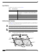
VIP4 Maintenance Procedures Figure 4 Location of CPU Memory and Packet Memory DIMMs on the VIP4 Bus connector CPU Packet memory DIMM U5 Port adapter in slot 1 26561 Port adapter in slot 0 CPU memory DIMM U1 Caution Note To prevent ESD damage, handle DIMMs by the card edges only. Place removed DIMMs on an antistatic mat and store them in an antistatic bag. Use only SDRAM DIMMs from Cisco Systems. A Cisco manufacturing part number appears on each SDRAM DIMM.
VIP4 Maintenance Procedures Figure 5 Opening the DIMM Socket Tabs 13339 Pull the tabs away with your thumbs, bracing your forefingers against the DIMM socket sides SDRAM DIMM Step 5 With the DIMM socket tabs open, grasp the ends of the DIMM between your thumbs and forefingers and pull the DIMM completely out of the socket. (See Figure 6.
VIP4 Maintenance Procedures Caution Step 6 To prevent ESD damage when working with DIMMs: handle the DIMM by the card edges only, place a removed DIMM on an antistatic mat, and store it in an antistatic container. Place the DIMM in an antistatic container to protect it from ESD damage. This completes the DIMM removal procedure. Installing SDRAM DIMMs Caution The DIMM is a sensitive component that is susceptible to ESD damage.
VIP4 Maintenance Procedures Step 6 If you have a network processing engine with more than one DIMM socket and are replacing the second DIMM also, repeat steps Step 1 through Step 5 above. This completes the DIMM replacement procedure. Reinstall the VIP4 in the system. (Follow the steps in the “Installing a VIP4” section on page 19.) See the following section, “Checking the VIP4 Memory Upgrade,” as required.
VIP4 Maintenance Procedures Figure 9 Handling a Port Adapter Metal carrier H6420 Printed circuit board Caution To prevent system problems, do not remove port adapters from the VIP4 motherboard or attempt to install other port adapters on the VIP4 motherboard while the system is operating. To install or replace port adapters, first remove the VIP4.
VIP4 Maintenance Procedures Figure 10 Removing and Installing a Single-Width Port Adapter Note: You must first remove the VIP from the chassis before removing a port adapter from the VIP4. A Step 1 To remove the port adapter, remove the screw that secures the port adapter (or blank port adapter). (See A.) Step 2 With the screw removed, grasp the handle on the front of the port adapter (or blank port adapter) and carefully pull it out of its slot, away from the edge connector at the rear of the slot.
VIP4 Maintenance Procedures Location of VIP4 Slot Divider and Screws 27871 Figure 11 Screw holes for septum Use the following procedure to remove the slot divider from a VIP4: Step 1 Attach an ESD-preventive wrist strap between you and an unpainted chassis surface. Step 2 Remove the VIP4 from the router. (See the “Removing a VIP4” section on page 18.) Step 3 Place the removed VIP4 on an antistatic mat or foam pad.
VIP4 Maintenance Procedures Figure 12 Removing and Installing a Dual-Width Port Adapter Note: You must first remove the VIP from the chassis before removing the dual-width port adapter from the VIP. Step 1 To remove the port adapter, remove the screws that secure the port adapter to the VIP. Step 2 With the screws removed, grasp the handles on the front of the port adapter and carefully pull it out of its slot, away from the edge connector at the rear of the slot. (See A.
VIP4 Troubleshooting VIP4 Troubleshooting To troubleshoot the VIP4, refer to Troubleshooting VIP Crashes online at http://www.cisco.com/warp/customer/63/vip_crash.html which requires user registration to access. To become a registered user, refer to http://www.cisco.com/register/. Listed below are common sense guidelines to troubleshoot the router, the VIP4 and its memory components, and the port adapter installation: • Verify that the router is plugged in.
Obtaining Technical Assistance • Registered Cisco.com users can order the Documentation CD-ROM through the online Subscription Store: http://www.cisco.com/go/subscription • Nonregistered Cisco.com users can order documentation through a local account representative by calling Cisco corporate headquarters (California, USA) at 408 526-7208 or, in North America, by calling 800 553-NETS (6387).
Obtaining Technical Assistance Technical Assistance Center The Cisco TAC website is available to all customers who need technical assistance with a Cisco product or technology that is under warranty or covered by a maintenance contract. Contacting TAC by Using the Cisco TAC Website If you have a priority level 3 (P3) or priority level 4 (P4) problem, contact TAC by going to the TAC website: http://www.cisco.
Obtaining Technical Assistance This document is to be used in conjunction with the documents listed in the “Related Documentation” section on page 2 section. CCSP, CCVP, the Cisco Square Bridge logo, Follow Me Browsing, and StackWise are trademarks of Cisco Systems, Inc.; Changing the Way We Work, Live, Play, and Learn, and iQuick Study are service marks of Cisco Systems, Inc.
Obtaining Technical Assistance Fourth Generation Versatile Interface Processor (VIP4) Installation and Configuration Guide 44 OL-3673-01