
User Guide


17
Fourth Generation Versatile Interface Processor (VIP4) Installation and Configuration Guide
OL-3673-01
VIP4 Installation Procedures
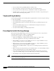
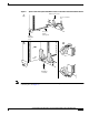
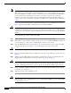
Figure 2 Ejector Levers and Captive Installation Screws on the VIP4—Vertical Orientation Shown
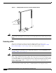
Note Handle processor modules by the carrier handles and carrier edges only; never touch the board or any
connector pins. (See Figure 3.)
H1482a
Processor module
slot
a
c
Stop
immediately
on contact
Bottom ejector lever
Captive
installation
screw
Processor
module
carrier guide
b