
User Guide


34
Fourth Generation Versatile Interface Processor (VIP4) Installation and Configuration Guide
OL-3673-01
VIP4 Maintenance Procedures
Caution To prevent ESD damage when working with DIMMs: handle the DIMM by the card edges only, place a
removed DIMM on an antistatic mat, and store it in an antistatic container.
Step 6 Place the DIMM in an antistatic container to protect it from ESD damage.
This completes the DIMM removal procedure.
Installing SDRAM DIMMs
Caution The DIMM is a sensitive component that is susceptible to ESD damage. Handle the DIMM by the edges
only; avoid touching the memory modules, pins, or traces (the metal fingers along the connector edge of
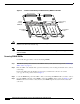
the DIMM). To prevent ESD damage, handle the DIMM as shown in Figure 7.
With the VIP4 in the same orientation as the previous procedure (with the handle away from you and the
bus connector toward you), use the following procedure to install the new DIMM in the DIMM socket:
Step 1 Remove the new DIMM from its antistatic container.
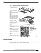
Step 2 Hold the DIMM between your thumbs and forefingers. (See Figure 7.)
Note The 64-MB DIMM should be facing component-side down.
Step 3 Insert the connector edge of the DIMM straight into the socket.
Caution When inserting the DIMM, use firm but not excessive pressure. If you damage a socket, you will have
to return the VIP4 to the factory for repair.
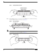
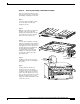
Step 4 Gently push the DIMM into the socket until the socket tabs close over the ends of the DIMM. (See
Figure 8.) If necessary, rock the DIMM gently back and forth to seat it properly.
Figure 8 Inserting the DIMM
Step 5 When the DIMM is installed, check to see it is seated properly. If the DIMM appears misaligned,
carefully remove it and reseat it in the socket. Push the DIMM firmly back into the socket until first one
and then the other socket tab moves into place.
13418