Ripwave Base Station ™ User Manual Part Number 40-00197-00 Revision C (1.20), Version 1.0 September 26, 2003 Proprietary All information disclosed by this document is the proprietary property of Navini Networks, Inc. and is protected by copyright, trademark, and/or trade secret laws. All rights therein are expressly reserved.
Base Station User Manual Navini Networks, Inc. About This Document Purpose This manual provides an overview for the Navini Networks Base Station. Topics included are installation of the Base Transceiver Station (BTS), Radio Frequency Subsystem (RFS), and cabling; and testing and commissioning the Base Station. Revision History Date Author Editor Comments Sept 17, 2003 Revision / Version A / 1.0 P. Prudhomme S. Redfoot Sept 18, 2003 Sept 26, 2003 B / 1.0 C / 1.0 P. Prudhomme P. Prudhomme S.
Navini Networks, Inc. Base Station User Manual Permissions, Trademarks & Distribution Copyright© September 2003, Navini Networks, Inc. All information contained herein and disclosed by this document is the proprietary property of Navini Networks, Inc. and all rights therein are expressly reserved. Acceptance of this material signifies agreement by the recipient that the information contained in this document is confidential and that it will be used solely for the purposes set forth herein.
Base Station User Manual Navini Networks, Inc. TABLE OF CONTENTS ABOUT THIS DOCUMENT ............................................................................................................. 2 PERMISSIONS, TRADEMARKS & DISTRIBUTION ........................................................................... 3 SAFETY ........................................................................................................................................ 5 REGULATORY INFORMATION ...........................
Navini Networks, Inc. Base Station User Manual Safety To optimize safety and expedite installation and service, read this document thoroughly. Follow all warnings, cautions, and instructions marked on the equipment and included in this document. To aid in the prevention of injury and damage to property, cautionary symbols have been placed in this document to alert the reader to known potentially hazardous situations, or hazards to equipment or procedures.
Base Station User Manual Navini Networks, Inc. disconnected from its power source. 9. Do not overload wall outlets, power strips, or extension cords. This can cause serious electrical shock or fire. 10. Do not place the equipment on an unstable surface. It can fall and cause injury or damage to the equipment. 11. Do not disassemble the equipment. Removing covers exposes dangerous voltages or other risks and also voids the warranty. Incorrect reassembly can cause equipment damage or electrical shock.
Navini Networks, Inc. Base Station User Manual Regulatory Information FCC Notice WARNING! This device is a Radio Frequency transmitter. It is required to comply with FCC RF exposure requirements for transmitting devices. A minimum separation distance of one meter or more must be maintained between the antenna and all persons during device operations to ensure compliance with the FCC’s rules for Radio Frequency Exposure.
Base Station User Manual Navini Networks, Inc. Battery Caution & Procedures WARNING! To reduce risk of injury or fire, follow these instructions when handling the battery. 1. Risk of explosion is possible if the battery is replaced with one not supplied by Navini Networks. 2. Do not dispose of the battery in a fire. It may explode. Check with the local codes for battery disposal guidelines. 3. Do not open or mutilate the battery.
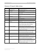
Navini Networks, Inc. Base Station User Manual Glossary of Terms & Abbreviations Term ACC ACK AP ARP ASYNCH ATM BB BCC BS BTS BW BYTE CAM CC CD Stands For.... Access Channel or Access Code Channel Acknowledge Meaning AKA, Paging Channel. The signal path that tells a mobile to prepare for an incoming call.
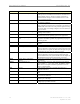
Base Station User Manual Term CDMA CD-ROM CHP CLEC CLI CORBA CPE dB dBd dBi DHCP DiffServ DIR DL DNS DS-1 DSL 10 Navini Networks, Inc. Stands For.... Code Division Multiple Access Meaning Digital cellular technology that uses a spread-spectrum technique where individual conversations are encoded with a random digital sequence. Increases capacity and speed of communications messages between mobile units over other types of wireless networks. Compact Disk - Read Only Memory See “CD.
Navini Networks, Inc. Term DSP Stands For....
Base Station User Manual Term L1 Stands For.... Layer 1 L2 Layer 2 L3 Layer 3 LAN Local Area Network LCP Link Control Protocol LED Light-emitting Diode LLC Logical Link Controller LOS Line-of-sight MAC Media Access Control Mb MB Mbps MDM Megabit Megabyte Megabits Per Second Modem Card MHz Megahertz MIB Management Information Base MMDS NE Multipoint Multi-channel Distribution Service 1 Near-end or 2Network Element NLOS Non Line-of-site 12 Navini Networks, Inc.
Navini Networks, Inc. Term NMS NOC OAM OS OSI PC PCB PDU Ping PPPoE Propagation PSK PSN PSTN QAM QoS Base Station User Manual Stands For.... Network Management System Meaning A product that helps manage a network generally hosted on a well-equipped computer such as an engineering workstation. The system tracks network statistics and resources.
Base Station User Manual Term RAM RF RFS RSSI Rx S-CDMA SMDS SMS SNMP SNR SSI SW SYN SYNCH TCC TCP TCP/IP 14 Navini Networks, Inc. Stands For.... Random Access Memory Radio Frequency Meaning Computer memory that can be accessed randomly. A portion of the electromagnetic spectrum in the frequency range between audio and infrared: 100 KHz to 20 GHz. RF measurements are expressed in Hz (unit for measuring frequency); MHz = 1 Million Hz; GHz = 1 Billing Hz.
Navini Networks, Inc. Term TDD Stands For.... Time Division Duplex TFFS True Flash File System TTL Time-to-live Tx Transmit UL UpLink USB Universal Serial Bus VCC Virtual Channel Circuit VCI Virtual Channel Identifier VCL Vector Virtual Channel Link Vector VPC Virtual Private Channel VP Virtual Path VPI Virtual Path Identifier VPL Virtual Path Link WAN 1 Wide Area Network or Wireless Access Network 2 Part #40-00047-01 Rev C v1.0 (1.
Base Station User Manual 16 Navini Networks, Inc. Part #40-00197-00 Rev C v1.0 (1.
Navini Networks, Inc. Base Station User Manual Overview Ripwave Description A Ripwave system has three main components: the Customer Premise Equipment (CPE); the Base Station; and the Element Management System (EMS). The Base Station performs the CPE registration and call processing, and provides the interface between the backhaul network and the EMS. It is made up of the Base Transceiver Station (BTS) and the Radio Frequency Subsystem (RFS) (Figure 1).
Base Station User Manual Navini Networks, Inc. Procedural Documents & Forms You will refer to other Ripwave documents, procedures, and forms in the process of installing and commissioning the Base Station. The product documentation is provided on the Ripwave Standard Documentation CD (Table 1). As well, the EMS manuals can be viewed on-line through the EMS Server and Client applications.
Navini Networks, Inc. Base Station User Manual High-level I&C Process To put the I&C activities in the context of overall system deployment, Figure 2 provides a ‘flow’ of the key activities that are performed prior to and during the installation and commissioning of the Ripwave Base Station. Post-I&C, the system that has been installed and commissioned goes through Acceptance Testing against the customer’s objectives for that site.
Base Station User Manual Navini Networks, Inc. Figure 2: High Level I&C Process Flowchart Phase I: Pre-installation - Site Selection, Design & Preparation BEGIN 1 - Complete the Project Plan for this deployment. Sample Statement of Work (SoW) Sample Responsibility Assignment Matrix (RAM) Sample Work Breakdown Structure (WBS) 2 - Generate a coverage prediction map. 3 - Conduct a site survey, filling out the Site Candidate Evaluation Form.
Navini Networks, Inc. Base Station User Manual Phase I: Pre-installation - Site Selection, Design & Preparation, continued A 6 - Complete the Network Architecture design. 7 - Antenna Power & Cable selection. Antenna Power & Cable Selection Procedure & Form 8 - Develop a Bill of Materials (BoM). Sample BoM 9 - Acquire the materials. 10 - Confirm the customer backhaul, EMS Server, FTP Server, input power and grounding are installed and operational at site.
Base Station User Manual Navini Networks, Inc. Phase II: Physical Installation 1 - From the shipping containers received at the customer site, gather Manufacturing’s inventory sheet and test data that was collected before the BTS & RFS equipment shipped. Verify all equipment arrived (inventory it), serial numbers match paperwork, and the test data is available. Keep this as part of the customer site records. 2 - Install all system buss bars and surge protectors. 3 - Cut cables.
Navini Networks, Inc. Base Station User Manual Installation, continued A 10 - Install & verify the DC input power source to the BTS. Sample Tri-sector BTS Power Drawing 11 - Install the GPS antennas. 12 - Sweep the RFS, per the Single Antenna Test Procedure. Record the results & the RFS serial numbers on the RFS System Test Form (same form as Step 3, Appendix O). Single Antenna Test Procedure 13 - Install the RFS & surge protectors. Connect the 9 RF cables & the data/power cable to the RFS.
Base Station User Manual Navini Networks, Inc. Installation, continued B 17 - If required in the Responsibility Assignment Matrix (RAM) portion of the Project Plan, test the backhaul to the customer demarcation point. 18 - Provide a printed package of the measured results and equipment inventory to the customer on-site. 19 - Go over the results using the printed package and obtain customer sign-off on the completion of the Installation portion of the work.
Navini Networks, Inc. Base Station User Manual Phase III: Commissioning 1 - Review the customer’s network plans - i.e., T1 vs Ethernet backhaul. 2 - Are you using the customer’s EMS Server? No Yes 3b - Install & configure the customer EMS Server & Client. Connect to the BTS. 3a - Install & configure the Test EMS Server & Client. Connect to the BTS. Excel Configuration Form 4 - Enter the RFS configuration by running the RFS script that shipped with the antenna equipment.
Base Station User Manual Navini Networks, Inc. Commissioning, continued A 8 - Did it pass calibration? No 9a - Perform system troubleshooting procedures. Yes Base Station Calibration Verification Form 9b - Perform Base Station calibration. Verify and record the measurements on the Base Station Calibration Verification Form. 10 - Did it pass calibration verification? No 11a - Perform system troubleshooting procedures. Yes Local Modem Test Procedures 11b - Perform local wired Modem test.
Navini Networks, Inc. Base Station User Manual Commissioning, continued B 13 - Perform the local overthe-air (OTA) Modem test. 14 - Did it pass the OTA Modem test? No - Go to 11a Yes 15 -Was the Test EMS used? No C Yes 16 - Install & configure the Customer EMS Server & Client. Connect to the BTS. 17 - Verify the EMS Server & BTS connectivity. 18 - Perform calibration. Ensure successful results 3 times. D Part #40-00047-01 Rev C v1.0 (1.
Base Station User Manual Navini Networks, Inc. Commissioning, continued *Note: Step 19 is performed only if no RF plot is available. D C 19* - Validate that the GPS & Constellation Debugger are installed and operational on the Drive Study laptop. Perform a Preliminary Drive Study. Record the results on the Drive Study Form. Drive Study Form 20 - Perform the Preliminary LOS Location (FTP) Test. Complete 3 uploads & 3 downloads at 3 locations. Record the results on the FTP Test Form.
Navini Networks, Inc. Base Station User Manual Commissioning, continued E 24b - Perform full Drive Study, and record the results on the Drive Study Form. This is used for tuning the model (same form as Step 19, Appendix X). 25 - Perform full LOS Location (FTP) Test. Record the results (same form as Step 20, Appendix Y). 26 - Perform full NLOS Location (FTP) Test. Record the results (same form as Step 20, Appendix Y). 27 - Send test results to Navini Technical Support.
Base Station User Manual Navini Networks, Inc. Base Station Components Base Transceiver Station (BTS) The BTS consists of the RF Power Amplifiers (PA’s), the digital circuit cards, the backplane, and the mechanical enclosure or housing. It performs the signal processing and RF transmission for the system. There are two types of chassis: Combo and Split. The Combo Chassis is used primarily with 2.4 GHz systems. The Split Chasses is used for all other (2.3, 2.5, 2.6 GHz) systems (Figure 3).
Navini Networks, Inc. Base Station User Manual Radio Frequency Subsystem (RFS) The Radio Frequency Subsystem (RFS) is mounted on a transmission tower or building rooftop. It transmits and receives data to and from the Ripwave Customer Premise Equipment (CPE) using a digital beamforming transmission technique. The RFS may be either a panel antenna or an omni antenna (Figure 4). An RFS panel transmits in a directional mode, covering a transmit angle of 120 degrees.
Base Station User Manual Navini Networks, Inc. Global Positioning System (GPS) One or two Global Positioning System (GPS) antennas are used with each Base Station. A GPS antenna works with a constellation of satellites that orbit the earth, and it provides the ability to pinpoint geographical locations. The two types of GPS antennas that may be ordered with a Ripwave Base Station are the VIC 100 and the Motorola Timing 2000 (Figure 5).
Navini Networks, Inc. Base Station User Manual Mounting Racks & Enclosures The BTS can be installed indoors or outdoors in industry standard 19- or 23-inch racks. Rack adapters are needed to mount the equipment in a standard 23-inch rack. For outdoor BTS’s, the customer can supply any standard enclosure from a multitude of vendors. Figure 6 shows 3 BTS’s installed indoors. Figure 6: Indoor BTS Data/Power Cable Part #40-00047-01 Rev C v1.0 (1.
Base Station User Manual Navini Networks, Inc. General Specifications Input Power The BTS requires +21 to 28 VDC power supply rated at 60 amps (combo chassis) and at 50 (RF shelf) and 20 (Digital shelf) for the split chassis. Installers are referred to industry standards for power supply installations. Humidity The operating environment of the BTS must control relative humidity to 5% to 95% RH, noncondensing.
Navini Networks, Inc. Base Station User Manual Base Station Specifications Current Ripwave operating frequencies include those shown in Table 3. Testing on other frequencies is underway and soon will be commercially available. The specifications are shown in Table 4. Table 3: Operating Frequencies Model 2.3 GHz Frequency Range 2.305 GHz to 2.
Base Station User Manual Up/down Link Duplex: Upgradeability: Weight: 36 Navini Networks, Inc. Symmetrical or Asymmetrical TDD with a maximum of 3:1 ratio for down/up allocations Software downloads Digital Shelf 35 lbs + RF Shelf 82 lbs. Part #40-00197-00 Rev C v1.0 (1.
Navini Networks, Inc. Base Station User Manual Materials Specifications The Base Station installation requires general materials and parts for installation. In Table 5 is a partial list of the items that may be used for a typical installation of the Ripwave Base Station. The quantity and use of materials will vary depending on the specific installation. The lists in Table 5 are based on a 150-foot site.
Base Station User Manual RFS Connector RFS Connector RFS Connector RFS Connector RFS Connector Weatherproofing RFS Cable RFS Cable RFS Cable RFS Cable GPS Antenna GPS Surge Protector GPS Surge Protector GPS Cable GPS Type N Male Connectors Goose Neck - J type Hood entry Feed Thru Entry Panel Boot Assembly Kits Ripwave 2400 BTS BTS Surge Protector 24 VDC Power Supply DC Power Wire DC Power Wire BREAKER ROUTER SERIAL WAN T1-IMA MODULE Air conditioning 110 VAC Power Outlets Telco / Ethernet Connectors RJ45 Na
Navini Networks, Inc. Base Station User Manual APPENDIX A: RFS IDENTIFICATION LABEL 2.3 GHz RFS – Omni High Band 2.72 +/-.03 Navini Networks Ripwave RFS Model No. 2300-RFS Part No. 95-23008-20 Freq Range: 2345-2360 MHz Electrical Down Tilt: 2° 3.58 +/-.03 RF SAFETY NOTICE: This antenna shall be mounted in accordance with the limits for Maximum Personnel Exposure (MPE) to radio frequency fields as per §1.1307 of the Rules of the Federal Communications Commission (FCC).
Base Station User Manual Navini Networks, Inc. 2.3 GHz RFS – Omni Low Band 2.72 +/-.03 Navini Networks Ripwave RFS Model No. 2300-RFS Part No. 95-23008-30 Freq Range: 2305-2320 MHz Electrical Down Tilt: 2° 3.58 +/-.03 RF SAFETY NOTICE: This antenna shall be mounted in accordance with the limits for Maximum Personnel Exposure (MPE) to radio frequency fields as per §1.1307 of the Rules of the Federal Communications Commission (FCC).
Navini Networks, Inc. Base Station User Manual 2.3 GHz RFS – Sector 2.72 +/-.03 2.72 +/-.03 Navini Networks Navini Networks Ripwave RFS Ripwave RFS Model No. 2300-RFS Part No. 95-23000-01 Freq Range: 2305-2320 MHz Electrical Down Tilt: 6° Model No. 2300-RFS Part No. 95-23000-06 Freq Range: 2345-2360 MHz Electrical Down Tilt: 6° 3.58 +/-.03 3.58 +/-.
Base Station User Manual 42 Navini Networks, Inc. Part #40-00197-00 Rev C v1.0 (1.
Navini Networks, Inc. Base Station User Manual APPENDIX B: 2.3 GHZ BTS IDENTIFICATION LABEL 2.72 +/-.03 2.72 +/-.03 Navini Networks Navini Networks Ripwave BTS Model No. Part No. Ripwave BTS 2300-DIGITAL 95-70003-05 Freq Range US: 2305-2320 MHz 2345-2360 MHz INT’L: 2375-2385 MHz FCC ID: PL6-WCS-BTS1 Model No. Part No. 3.00 +/-.03 2300-RF 95-50003-01 Freq Range US: 2305-2320 MHz 2345-2360 MHz INT’L: 2375-2385 MHz 3.00 +/-.03 FCC ID: PL6-WCS-BTS1 CLEAR WINDOW FOR NAVINI BAR CODE (1.5000 X .