
User Manual
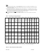
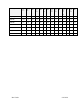
Table Of Contents

I&C Guide 9/26/2003
Appendix L: Antenna Power & Cable Selection
Overview
This section provides formulas and data that are necessary inputs for determining the right cable to be
measured, cut, and installed. There are 3 types of cables that are part of the Base Station installation: antenna
cables, calibration (cal) cable, and data/power cable.
The antenna cables are the eight cables that carry amplified RF signals. They run between the RF/PA cards
and the 8 antenna elements. The calibration (cal) cable is a single RF coaxial cable that provides an RF
feedback path for calibrating the system. It runs between the backplane of the digital shelf and the RFS. The
data/power cable may or may not be a separate cable from the cal cable. It is possible to use different types of
cable with different loss factors for the antenna cables and cal cable. The formulas presented in this section
call for either an antenna cable loss or a cal cable loss. Most applications deploy the same cable type for both
the antenna and cal cables.
To determine the type of cable and acceptable loss of that cable for a site, the operating transmit and receive
range must be known. This is commonly referred to as the maximum transmit output power and the receiver
sensitivity range. The operating transmit power and receive range should have been identified during the site
survey, or they may be based on regulatory compliance.
Determining the cable type and acceptable loss for a site are typically driven by two goals: (1) Which is the
least expensive cable; and (2) Which has the higher (normally) loss. Whether or not the goals are achieved is
determined by the output power. For example, the maximum transmit output power for a 2.6 Base Station
might be given as +30dBm, or 1 Watt, to the antenna. An example of receiver sensitivity for a 2.6 system
would be given as – 80 to –90 dBm.
In addition to cable power loss, other types of loss have to be factored - for example, the calibration board.
The calibration board is part of the RFS that samples the energy being transmitted from or received by the 8
antenna elements and combines that energy which is used when performing a calibration on the Base Station.
This loss, plus cable loss and other types of loss in the equipment are called out in the following procedure.
Procedure
Read and follow the 7 steps/formulas below, in the order shown, to determine the resulting PA/RFS output
power and desired transmit and receive calibration range for the type of Base Station you will be installing.
Refer to Tables L1 and L2 to complete the steps. Table L1 provides Base Station operating parameters based
on system type (2.3, 2.4, etc.), as well as other variables. Table L2 provides cable attenuation data. Before you
begin, read through the steps/formulas, notes, and Table L1 in detail. Refer to the column letters at the top of
Table L1 to locate the appropriate values requested in some of the formulas. Note that step/formula 1 contains
a sub-procedure for determining antenna cable loss using Table L2.