Catalyst 6500 Series Switch and Cisco 7600 Series Router CMM Installation and Verification Note Product Number: WS-SVC-CMM This publication contains the procedures for installing and configuring the Catalyst 6500 series switch and Cisco 7600 series router Communication Media Module (CMM).
Contents Contents This publication contains these sections: • Front Panel Descriptions, page 2 • Requirements, page 6 • Safety Overview, page 7 • Required Tools, page 9 • Installing and Removing the CMM, page 9 • Removing and Replacing Port Adapters, page 18 • Verifying the Installation, page 24 • RJ-45 Port Connector and Cabling Specifications, page 24 • RJ-21 Port Connector and Cabling Specifications, page 26 • Accessing the Port Adapter Ports, page 27 • Configuring the Port Adapter
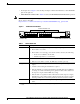
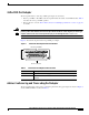
Front Panel Descriptions Note • Port adapter slots—Figure 1 shows the E1 port adapter in the left and middle slots, with a blank filler plate in the right slot. • REAR MODULE STATUS LED—Table 2 describes the REAR MODULE STATUS LED operation. For information on the supervisor engine LEDs, refer to the Catalyst 6500 Series Switch Supervisor Engine Guide at this URL: http://www.cisco.com/univercd/cc/td/doc/product/lan/cat6000/6000hw/supe_gd/index.
Front Panel Descriptions Table 2 CMM Rear Module STATUS LED Color Description Green Port adapter in slot 4 is up and operational. Red Port adapter in slot 4 is shut down. No light Slot 4 port adapter is not located by the system. 6-Port T1 and E1 Port Adapters The front panel features of the 6-port T1 and E1 port adapters are as follows: • Receive port LEDs—The LEDs on the front panel indicate the status of each T1 and E1 interface. Table 3 describes the receive port LED operation.
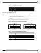
Front Panel Descriptions 24-Port FXS Port Adapter The front panel features of the 24-port FXS port adapter are as follows: Warning • Receive port LEDs—The LEDs on the front panel indicate the status of each FXS interface. Table 4 describes the receive port LED operation. • RJ-21 connector—See the “RJ-21 Port Connector and Cabling Specifications” section on page 26 for details.
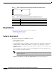
Requirements Figure 4 Ad-hoc Conferencing and Transcoding Port Adapter Front Panel Features Ad-hoc Conferencing and Transcoding Port Adapter Table 5 99302 WS-SVC-CMM-ACT Ad-hoc Conferencing and Transcoding Port Adapter STATUS LED Color Description Green Port adapter is up and operational. Red Port adapter is shut down. Off Port adapter is not located by the system.
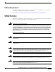
Safety Overview Software Requirements For software requirements, refer to the Release Notes for the Cisco Catalyst 6500 Series and the Cisco 7600 Series Communication Media Module at this URL: http://www.cisco.com/univercd/cc/td/doc/product/lan/cat6000/mod_icn/cmm/index.htm Safety Overview Throughout this publication, safety warnings appear in procedures that, if performed incorrectly, can harm you. A warning symbol precedes each warning statement.
Safety Overview Warning Blank faceplates and cover panels serve three important functions: they prevent exposure to hazardous voltages and currents inside the chassis; they contain electromagnetic interference (EMI) that might disrupt other equipment; and they direct the flow of cooling air through the chassis. Do not operate the system unless all cards, faceplates, front covers, and rear covers are in place.
Required Tools Required Tools Warning Only trained and qualified personnel should be allowed to install, replace, or service this equipment.
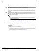
Installing and Removing the CMM To install the CMM into the Catalyst 6500 series switch or the Cisco 7600 series router, perform these steps: Step 1 Make sure that you take the necessary precautions to prevent ESD damage. Step 2 Choose a slot for the CMM. Step 3 Verify that there is enough clearance to accommodate any interface equipment that you will connect directly to the module ports. If possible, place modules between empty slots that contain only module filler plates.
Installing and Removing the CMM Figure 5 Positioning the Module in a Horizontal Slot Chassis Insert module between slot guides EMI gasket 3 4 5 6 4 5 6 WS-X6K-SUP2-2GE 1 T E US NS ST SY GM OL EM AT ST R CO M Switch 100% T SE PW Load CONSOLE PORT MODE RE PORT 1 PORT 2 CONSOLE SUPERVISOR2 PCMCIA EJECT 1% WS-X6K-SUP2-2GE 2 T E US NS ST SY GM OL EM AT ST CO R PW M Switch 100% T SE Load CONSOLE PORT MODE RE PORT 1 PORT 2 CONSOLE SUPERVISOR2 PCMCIA
Installing and Removing the CMM Figure 6 Clearing the EMI Gasket in a Horizontal Slot Chassis WS-X6K-SUP2-2GE 1 US AT ST LE EM ST SY O NS CO PW M R G M T Switch 100% T SE RE CONSOLE Load CONSOLE PORT MODE SUPERVISOR2 PORT 1 PCMCIA PORT 2 EJECT 1% WS-X6K-SUP2-2GE NK LI 2 US AT ST LE EM ST SY O NS CO PW M R G M Switch 100% T SE RE CONSOLE SUPERVISOR2 NK LI T CONSOLE PORT MODE Load PORT 1 PCMCIA PORT 2 EJECT 1% NK LI NK LI 3 Press down 4 FAN
Installing and Removing the CMM Figure 7 Ejector Lever Closure in a Horizontal Slot Chassis WS-X6K-SUP2-2GE 1 US AT ST LE EM ST SY O NS CO PW R M G M T Switch 100% T SE RE CONSOLE SUPERVISOR2 Load CONSOLE PORT MODE PORT 1 PCMCIA PORT 2 EJECT 1% WS-X6K-SUP2-2GE NK LI 2 US AT ST EM ST SY M G O NS R CO NK LI T LE PW M Switch 100% T SE RE CONSOLE SUPERVISOR2 Load CONSOLE PORT MODE PORT 1 PCMCIA PORT 2 EJECT 1% NK LI NK LI 3 4 FAN STATUS 5 WS-
Installing and Removing the CMM Figure 8 Positioning the Module in a Vertical Slot Chassis Ejector lever fully extended WS-C6500-SFM SWITCH FABRIC MDL FAN STATUS WS-X6K-SUP2-2GE MT E M S OL T MG TU R NS SE STE RE PW CO SY STA MT OLE MG TEM NS TUS R SET RE PW SYS CO STA WS-X6K-SUP2-2GE SUPERVISOR2 SUPERVISOR2 ST AT CONSOLE CONSOLE US AC PORT MODE PORT MODE CONSOLE WS-X6224 24 PORT 100FX CONSOLE TIV E US AT ST E TIV AC PCMCIA PCMCIA EJECT EJECT Switch Switch 1% 100% 1% 100%
Installing and Removing the CMM Figure 9 Clearing the EMI Gasket in a Vertical Slot Chassis Gap between the module EMI gasket and the module above it 1 mm WS-C6500-SFM SWITCH FABIRD MDL S TU A ST E TIV AC FAN STATUS WS-X6K-SUP2-2GE MT E M S OL T MG TU R NS SE STE RE PW CO SY STA US AT ST MT OLE MG TEM NS TUS R SET RE PW SYS CO STA WS-X6K-SUP2-2GE SUPERVISOR2 SUPERVISOR2 WS-X6224 24 PORT 100FX CONSOLE CONSOLE E TIV AC PORT MODE PORT MODE CONSOLE CONSOLE Press left PCMCIA PCMCIA E
Installing and Removing the CMM Figure 10 Ejector Lever Closure in a Vertical Slot Chassis FAN STATUS T M LE G O T M EM US R NS SE ST AT RE PW SY CO ST CO EM ST SY O NS PW LE STA R T CONSOLE CONSOLE VE TI AC SE T M RE G S M TU CONSOLE PORT MODE CONSOLE PORT MODE PCMCIA PCMCIA EJECT EJECT 1% Switch Switch 100% 1% 100% Load Load PORT 1 PORT 1 XT WS-X6K-SUP2-2GE SUPERVISOR2 US AT ST WS-X6K-SUP2-2GE SUPERVISOR2 WS-X6224 24 PORT 100FX NE SE LE CT 63587 PORT 2
Installing and Removing the CMM To remove a module from the chassis, perform these steps: Step 1 Disconnect any network interface cables that are attached to the module. Step 2 Verify that the captive installation screws on all of the modules in the chassis are tight. This step assures that the space that is created by the removed module is maintained.
Removing and Replacing Port Adapters Removing and Replacing Port Adapters Follow the procedures in this section to remove and replace the port adapters on the CMM: • Removing a Port Adapter from CMM Slots 1 through 3, page 18 • Installing a Port Adapter in CMM Slots 1 through 3, page 21 • Installing and Removing an Ad-Hoc Conferencing and Transcoding Port Adapter in Slot 4, page 22 Removing a Port Adapter from CMM Slots 1 through 3 Note When you face the CMM front panel, slot 1 is on the left, slot
Removing and Replacing Port Adapters To install the CMM into the Catalyst 6500 series switch or the Cisco 7600 series router, see the “Installing the CMM” section on page 9.
Removing and Replacing Port Adapters Figure 12 CMM (Top View with Port Adapters Installed) Slot 4 standoffs (2) Slot 4 Phillips screws (2) Standoffs (6) 1 2 3 4 5 6 WS-X6600-6EI 1 2 3 4 5 6 S TA T U S WS-X6600-6TI R S EA TA R T U MD S L WS-X6600 AVVID Services Module Figure 13 6Port TI Intfc Mdl 6Port EI Intfc Mdl 68453 Phillips screws (6) CMM (Top View with Port Adapters Removed) Slot 4 connectors (2) Slot 4 Phillips screw mounting posts (2) Slot 4 standoff mounting posts
Removing and Replacing Port Adapters Installing a Port Adapter in CMM Slots 1 through 3 Note When you face the CMM front panel, slot 1 is on the left, slot 2 is in the middle, and slot 3 is on the right. Slot 4 is located internally. (See Figure 13.) To install a port adapter in CMM slots 1 through 3, perform these steps: Warning Hazardous voltage or energy is present on the backplane when the system is operating. Use caution when servicing.
Removing and Replacing Port Adapters Caution Using the screws or standoffs to seat the port adapter could warp the port adapter. Before you install and tighten the securing screws, ensure that the port adapter is fully seated by visually verifying that the bottom of the port adapter is in contact with the top of the mounting posts. Step 8 Install the two standoffs and two Phillips screws to secure the port adapter. (See Figure 12.
Removing and Replacing Port Adapters Step 4 In Figure 13, note the location of the two slot 4 standoff mounting posts. Remove the two mounting posts that secure the port adapter. Step 5 In Figure 13, note the location of the two slot 4 connectors. Carefully remove the port adapter, taking care when lifting up and disconnecting the port adapter from the connectors.
Verifying the Installation Caution Using the screws or standoffs to seat the port adapter could warp the port adapter. Before you install and tighten the securing screws, ensure that the port adapter is fully seated by visually verifying that the bottom of the port adapter is in contact with the top of the mounting posts. Step 6 Install the two standoffs and two Phillips screws to secure the port adapter. (See Figure 12.
RJ-45 Port Connector and Cabling Specifications Warning Hazardous network voltages are present in WAN ports regardless of whether power to the unit is OFF or ON. To avoid electric shock, use caution when working near WAN ports. When detaching cables, detach the end away from the unit first. Statement 1026 Warning To avoid electric shock, do not connect safety extra-low voltage (SELV) circuits to telephone-network voltage (TNV) circuits.
RJ-21 Port Connector and Cabling Specifications RJ-21 Port Connector and Cabling Specifications Warning Caution If the symbol of suitability with an overlaid cross appears above a port, you must not connect the port to a public network that follows the European Union standards. Connecting the port to this type of public network can cause severe personal injury or can damage the unit.
Accessing the Port Adapter Ports Table 7 RJ-21 Connector Pinouts Port Number Connector Pin Number Signal Port Number Connector Pin Number Signal 1 1 26 Ring Tip 13 13 38 Ring Tip 2 2 27 Ring Tip 14 14 39 Ring Tip 3 3 28 Ring Tip 15 15 40 Ring Tip 4 4 29 Ring Tip 16 16 41 Ring Tip 5 5 30 Ring Tip 17 17 42 Ring Tip 6 6 31 Ring Tip 18 18 43 Ring Tip 7 7 32 Ring Tip 19 19 44 Ring Tip 8 8 33 Ring Tip 20 20 45 Ring Tip 9 9 34 Ring Tip 21 21 46 Ring Tip
Configuring the Port Adapter Ports Configuring the Port Adapter Ports Configuring the CMM interfaces is similar to configuring the voice interfaces on other Cisco products. CMM interface configuration requirements are dependent on your AVVID network requirements. For interface configuration procedures, refer to the Cisco IOS Voice, Video, and Fax documentation for your release at this URL: http://www.cisco.com/univercd/cc/td/doc/product/software/index.htm Note The CMM requires a static IP address.
Disaster Recovery for CMM Software Upgrades Disaster Recovery for CMM Software Upgrades Note Disaster recovery is supported only on systems that are using Catalyst operating system software on the supervisor engine. This section describes how to recover in the event that the CMM software image fails to load properly. If there is a corrupted image in the CMM bootflash, the CMM does not come online and stays at the ROMMON prompt.
Disaster Recovery for CMM Software Upgrades Step 5 Enter the set poll disable command to disable polling. Step 6 Enter the set module power up mod command to power up the CMM. When the CMM powers up, disaster recovery is complete. Step 7 After you complete the disaster recovery, enter the clear filename-alias slot0:ws-svc-cmm command to terminate the filename translation. Step 8 Set the power management bits of the CMM to zero (0).
Regulatory Standards Compliance Step 7 After you complete the disaster recovery, enter the clear filename-alias disk0:ws-svc-cmm command to terminate the filename translation. Step 8 After you complete the disaster recovery, set the power management bits of the CMM to zero (0). This step is necessary to prevent the download mechanism from triggering every time that the CMM is reset. Step 9 Enter the set poll enable command to enable polling.
Obtaining Documentation Obtaining Documentation Cisco documentation and additional literature are available on Cisco.com. Cisco also provides several ways to obtain technical assistance and other technical resources. These sections explain how to obtain technical information from Cisco Systems. Cisco.com You can access the most current Cisco documentation at this URL: http://www.cisco.com/univercd/home/home.htm You can access the Cisco website at this URL: http://www.cisco.
Documentation Feedback Documentation Feedback You can send comments about technical documentation to bug-doc@cisco.com. You can submit comments by using the response card (if present) behind the front cover of your document or by writing to the following address: Cisco Systems Attn: Customer Document Ordering 170 West Tasman Drive San Jose, CA 95134-9883 We appreciate your comments. Cisco Product Security Overview Cisco provides a free online Security Vulnerability Policy portal at this URL: http://www.
Obtaining Technical Assistance In an emergency, you can also reach PSIRT by telephone: • 1 877 228-7302 • 1 408 525-6532 Obtaining Technical Assistance For all customers, partners, resellers, and distributors who hold valid Cisco service contracts, Cisco Technical Support provides 24-hour-a-day, award-winning technical assistance. The Cisco Technical Support Website on Cisco.com features extensive online support resources.
Obtaining Additional Publications and Information To open a service request by telephone, use one of the following numbers: Asia-Pacific: +61 2 8446 7411 (Australia: 1 800 805 227) EMEA: +32 2 704 55 55 USA: 1 800 553-2447 For a complete list of Cisco TAC contacts, go to this URL: http://www.cisco.com/techsupport/contacts Definitions of Service Request Severity To ensure that all service requests are reported in a standard format, Cisco has established severity definitions.
Obtaining Additional Publications and Information • iQ Magazine is the quarterly publication from Cisco Systems designed to help growing companies learn how they can use technology to increase revenue, streamline their business, and expand services. The publication identifies the challenges facing these companies and the technologies to help solve them, using real-world case studies and business strategies to help readers make sound technology investment decisions.