
Specifications

2-9
Cisco ONS 15454 Troubleshooting and Maintenance Guide
November 2001
Chapter 2 General Troubleshooting
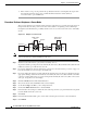
Step 12 Confirm that the newly-created circuit appears with a direction column noting that this circuit is 1-way.
Step 13 If the test set is not already sending traffic, send test set traffic on the loopback circuit.
Step 14 Examine the test traffic received by the test set. Look for errors or any other signal information that the
test set is capable of indicating.
Step 15 If the test set indicates a good circuit, skip to the “Perform a Hairpin on a Destination Node” procedure
on page 2-10.
Step 16 If the test traffic is not received or is poor quality, there may be a problem with the cross-connect card.
Caution Cross-connect manual switches (side switches) are service-affecting. Any live traffic on any
card in the node endures a hit of up to 50 ms.
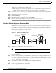
Step 17 Perform a software reset on the standby cross-connect card:
a. Determine the standby cross-connect card. On both the physical node and the CTC screen, the
ACT/STBY LED of the standby cross-connect card is amber, and the ACT/STBY LED of the active
cross-connect card is green.
b. Position the cursor over the standby cross-connect card.
c. Right-click to choose RESET CARD.
Step 18 Do a manual switch (side switch) of the cross-connect cards before retesting the circuit:
a. Determine the standby cross-connect card. The ACT/STBY LED of the standby cross-connect card
is amber, and the ACT/STBY LED of the active cross-connect card is green.
Note Place the cursor on top of the card graphic to display a dialog. This display identifies the
card as XC: Active or XC: Standby.
b. In the node view, select the Maintenance > XC Cards tabs.
c. From the Cross Connect Cards menu, choose Switch.
d. Click Yes on the Confirm Switch dialog box.
Note After the active cross-connect goes into standby, the original standby slot becomes
active. This causes the ACT/STBY LED to become green on the former standby card.
Step 19 Retest the circuit:
a. Resend test set traffic on the loopback circuit.
The test set traffic now travels through the alternate cross-connect card.
b. Examine the test traffic received by the test set. Look for errors or any other signal information that
the test set is capable of indicating.
c. If the signal received by the test set is still faulty or non-existent, assume the cross-connect card is
not causing the problem. Proceed to the “Perform a Hairpin on a Destination Node” procedure on
page 2-10.
Step 20 If the circuit is now good, the problem could be a defective card. To confirm a defective original
cross-connect card:
a. Redo the manual switch (side switch) procedure to make the original active cross-connect card again
the active card.