About This Guide This section discusses the audience, organization, and conventions of this installation and configuration guide. Cisco documentation and additional literature are available in a CD-ROM package, which ships with your product. The Documentation CD-ROM, a member of the Cisco Connection Family, is updated monthly. Therefore, it might be more current than printed documentation.
Installation Guide Overview Installation Guide Overview This guide contains the following chapters and appendices: • About This Guide—Provides an overview of and describes conventions of this document. • Overview of the Router—Provides an overview of the router models, including connector descriptions, types of networks supported by each model, and product features. • • Installing the Router—Describes how to make LAN and WAN network connections.
Installation Guide Conventions • Braces contain a choice of keywords (represented by x below) that are separated by vertical bars: {x|x|x} • Angled brackets contain characters that are not echoed on the screen, such as passwords: • The key labeled Control is represented by ^ or Ctrl-D. For example, when you read ^D or Ctrl-D, you should hold down the Control key while you press the D key. Note Means reader take note.
Installation Guide Conventions Attention Ce symbole d'avertissement indique un danger. Vous vous trouvez dans une situation pouvant causer des blessures ou des dommages corporels. Avant de travailler sur un équipement, soyez conscient des dangers posés par les circuits électriques et familiarisez-vous avec les procédures couramment utilisées pour éviter les accidents. Warnung Dieses Warnsymbol bedeutet Gefahr. Sie befinden sich in einer Situation, die zu einer Körperverletzung führen könnte.
C H A PT E R 1 Overview of the Router Cisco 1600 series routers are a family of small desktop routers that link small-to-medium remote Ethernet LANs to regional and central offices over multiple WAN connections.
Router Features Router Features Note The Cisco 1600 series routers are either run-from-flash (RFF) or run-from-RAM (RFR) models. Router model names with an R are RFR routers; all other models are RFF. In this document, model names without an R refer to both RFF and RFR models, except where noted. The “Router Memory” section later in this chapter describes the differences between RFF and RFR models.
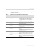
Router Features Table 1-1 describes in detail the types of LAN and WAN connections that are supported by each of the five router models. Table 1-1 Network Connections Supported By Cisco 1600 Series Routers Model LAN Interface(s) Fixed WAN Interface Cisco 1601 • One 10BaseT Serial: • One AUI1 • Supports synchronous modes, such as leased lines, Frame Relay, 56-kbps services, SMDS, and X.25, up to 2.048 Mbps (EIA/TIA-232, V.35, X.21, EIA/TIA-499, EIA-530).
WAN Interface Cards WAN Interface Cards On the Cisco 1601 through Cisco 1604, you can use the WAN interface card connection as a secondary WAN connection, which can be used if the router on-board WAN connection fails. On the Cisco 1605, you can choose the type of WAN connection that you want for your network. For more information about the cards, including function, installation, and configuration, refer to the Cisco WAN Interface Cards Hardware Installation Guide document that comes with the card.
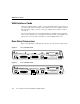
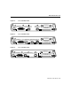
Rear-Panel Connectors Figure 1-4 Cisco 1603 Rear Panel DO NOT INSTALL ANY WAN MODULE WITH POWER ON AUI LNK Figure 1-5 CONSOLE ISDN BRI Ø S/T WIC OK OK FLASH PC CARD 14 VDC H7185 ETHERNET Ø 10 BASE T Cisco 1604 Rear Panel DO NOT INSTALL ANY WAN MODULE WITH POWER ON AUI ISDN BRI Ø U ISDN PHONE NT 1 OK LNK Figure 1-6 CONSOLE WIC OK FLASH PC CARD 14 VDC H7186 ETHERNET Ø 10 BASE T Cisco 1605 Rear Panel DO NOT INSTALL ANY WAN MODULE WITH POWER ON LNK ETHERNET Ø AUI ETHERNET 1
Rear-Panel Connectors Table 1-2 describes the connectors on the rear panel of the router. Table 1-2 Function—Rear Panel Connectors and Slots Label Router Model ETHERNET Ø All Function • 10BASE T • Connects the router to a 10BaseT Ethernet LAN through an Ethernet hub or switch. • AUI • Connects the router to an Ethernet LAN through a transceiver. CONSOLE All Connects the router to a terminal or to a PC running terminal emulation software for configuration.
Router Memory Router Memory The Cisco 1600 series routers are either of run-from-flash (RFF) or run-from-RAM (RFR) models. Router model names with an R are RFR routers; all other models are RFF. In this document, model names without an R refer to both RFF and RFR models, except where noted. This section describes the two memory architectures used in the Cisco 1600 series routers.
Router Memory Run-From-RAM Architecture With RFR, the Cisco IOS image is stored in Flash memory (usually in compressed form), but is loaded into RAM before being used to operate the router. The running software image then resides in RAM, so a new software image can be downloaded and copied over the software image stored in Flash memory. In RFR routers, only a minimal boot-helper image is stored in the ROM for disaster recovery.
Run-From-RAM Architecture Table 1-3 Memory Architecture Comparison (Continued) Feature Run-From-Flash Routers Run-From-RAM Routers Flash PC card capacity • Standard: 4 MB • Standard: 2 MB • Maximum: 12 MB • Maximum: 12 MB • Cisco IOS software image can be downloaded over any interface and with any WAN protocol supported by the ROM boot helper. • Cisco IOS software image can be downloaded with the ROM boot helper over the Ethernet 0 interface.
Router Memory Identifying the Memory Architecture from Cisco IOS Use the Cisco IOS show version command to display some memory architecture information for your router (show in boldface in the example output): • • • Amount of onboard DRAM (a type of RAM) Whether the Cisco IOS software is running from RAM or Flash memory Amount of Flash memory Router# show version Cisco Internetwork Operating System Software IOS (tm) 1600 Software (C1600-BNSY-M), EARLY DEPLOYMENT RELEASE SOFTWARE 11.
Unpacking the Router Unpacking the Router Figure 1-7 shows the other items that come with your router. All of these are in the accessory kit that is inside the box that your router came in.
Unpacking the Router Figure 1-7 Router Box Contents ion tat en cum OM Do D-R C Cisco 1600 router Hardw a Install re ation Guide Softw Confi are gurati o Guide n Product documentation Power supply 1-12 Console cable (light blue, RJ-45-to-RJ-45) DB-9-to-RJ-45 console adapter (light gray) Flash PC card (Already installed in router) DB-25-to-RJ-45 console adapter (light gray) Cisco 1600 Series Router Hardware Installation Guide H10382 Power cord (black)
Equipment That You Must Provide Equipment That You Must Provide Figure 1-8 shows items that you will have to provide to install your router. You will require only some of these items, depending on what Cisco 1600 model you are installing. Figure 1-8 Items That You Provide RJ-48S-to-RJ-48S cable (If installing a Cisco 1602. An RJ-45-to-RJ-45 straight-through cable can substitute.
Equipment That You Must Provide 1-14 Cisco 1600 Series Router Hardware Installation Guide
C H A PT E R 2 Installing the Router This chapter contains hardware installation procedures for Cisco 1600 series routers and includes the following sections: • • • • • Before Installing Connecting Power and Turning On the Router Connecting the Router to the LAN Connecting the Router to the WAN Connecting the Console Port Note You might want to perform some optional installation steps that are not explained in this chapter, including wall-mounting the router, installing the Flash PC card, connecting a
Connecting Power and Turning On the Router Caution Do not place anything on top of the router that weighs more than 10 pounds (4.5 kg). Excessive weight on top of the router could damage the chassis. Warning Do not work on the system or connect or disconnect cables during periods of lightning activity. Connecting Power and Turning On the Router If you turn on the router before making network connections, you can verify your installation by checking the appropriate LEDs during the installation process.
Connecting Power and Turning On the Router Check the following LEDs: • The SYSTEM PWR LED (front panel)—On when power is being supplied to router. • The SYSTEM OK LED (front panel)—On when router software is operational. (This LED first blinks and then remains on continuously.) • The OK LED (rear panel, next to Flash PC card slot)—On when the Flash memory card is correctly installed.
Connecting the Router to the LAN Connecting the Router to the LAN The router can be connected to two 10BaseT or AUI Ethernet LANs. Warning Do not work on the system or connect or disconnect cables during periods of lightning activity. Warning The ports labeled 10BASET, CONSOLE, and FLASH PC CARD are safety extra-low voltage (SELV) circuits. SELV circuits should only be connected to other SELV circuits.
Connecting to an AUI Ethernet Step 4 • The transceiver power LED (the location depends on model)—On when power is supplied to the transceiver through the router. • The LAN ACT LED (front panel)—Blinks when there is traffic on the Ethernet LAN.
Connecting the Router to the LAN Connecting to a 10BaseT Ethernet You must supply an Ethernet hub and an RJ-45-to-RJ-45 cable for this connection. Follow these steps to connect the router to a 10BaseT Ethernet LAN: Figure 2-3 Step 1 Connect one end of the Ethernet cable to the 10BASE T port. Step 2 Connect the other end of the cable to one of the ports on the 10BaseT hub.
Cisco 1605 LAN Connections Cisco 1605 LAN Connections Unlike the other Cisco 1600 models, the Cisco 1605 can support two LAN connections (Figure 2-4). The Cisco 1605 has two Ethernet Ø ports. However, you can use only one of the Ethernet Ø ports at any one time. A second Ethernet connection must always be on the ETHERNET 1 10BASE T port.
Connecting the Router to the LAN Figure 2-4 Cisco 1605 with Two Ethernet LAN Connections Ethernet AUI port (DB-15) (with jackscrews or slide-latch) LNK OK WIC DO NOT MOD INST ALL ULE WITH ANY POW WAN ER ON OK OK Router Ethernet transceiver 10BaseT hub BNC connector AUI 8 To thin Ethernet network 7 6 5 Straight-through Ethernet cable 2-8 4 3 2 1 H10603 To thin Ethernet network Cisco 1600 Series Router Hardware Installation Guide
Connecting the Router to the WAN Connecting the Router to the WAN Each Cisco 1600 series router supports a different type of WAN connection. This section describes how to make these WAN connections: • • • • • Cisco 1601—Serial Cisco 1602—Data service unit/channel service unit (DSU/CSU) Cisco 1603—ISDN BRI S/T Cisco 1604—ISDN BRI U Cisco 1605—Refer to the Cisco WAN Interface Cards Hardware Installation Guide that came with your WAN interface card.
Connecting the Router to the WAN Follow these steps to connect the Cisco 1601 to the WAN: Step 1 Connect the cable DB-60 connector to the SERIAL Ø port on the Cisco 1601. Step 2 Connect the other end of the cable to one of the following devices: Step 3 Asynchronous modem that you provide if connecting to an analog telephone line. • Synchronous modem, DSU/CSU, or other data circuit-terminating equipment (DCE) that you provide if connecting to a digital WAN line. Check the RDY LED on the rear panel.
Connecting the Cisco 1602 to the WAN Connecting the Cisco 1602 to the WAN You must provide either an RJ-48S-to-RJ-48S or an RJ-45-to-RJ-45 cable for this step. Follow these steps to connect the Cisco 1602 to the WAN: Step 1 Connect one end of the cable to the router SERIAL Ø 56K DSU/CSU port. Step 2 Connect the other end of the cable to the 56-kbps wall jack (Figure 2-6).
Connecting the Router to the WAN Connecting the Cisco 1603 to the WAN You must provide a Network Termination 1 (NT1) device and a straight-through RJ-45-to-RJ-45 cable for this connection. Warning Network hazardous voltages are present in the BRI cable. If you detach the BRI cable, detach the end away from the router first to avoid possible electric shock. Network hazardous voltages also are present on the system card in the area of the BRI port (RJ-45 connector), regardless of when power is turned off.
Connecting the Cisco 1603 to the WAN Figure 2-7 NT1 Connection—Cisco 1603 LN K LN K WI C OK OK ISDN S/T port Router H7201 ISDN link OK LED Straight-through RJ-45-to-RJ-45 cable NT1 device S/T port Installing the Router 2-13
Connecting the Router to the WAN ISDN Wall Jack Connection—Cisco 1603 H3587 Figure 2-8 Wall jack Straight-through BRI cable Warning Network hazardous voltages are present in the BRI cable. If you detach the BRI cable, detach the end away from the router first to avoid possible electric shock. Network hazardous voltages also are present on the system card in the area of the BRI port (RJ-45 connector), regardless of when power is turned off.
Connecting the Cisco 1604 to the WAN Connecting the Cisco 1604 to the WAN You must provide a straight-through cable, either RJ-11-to-RJ-11 or RJ-45-to-RJ-45, for this connection. Follow these steps to connect the Cisco 1604 to the WAN: Step 1 Connect one end of the cable to the ISDN Ø U port on the router. Step 2 Connect the other end of the cable directly to the ISDN BRI wall jack (Figure 2-9).
Connecting the Console Port Connecting the Cisco 1605 to the WAN The procedure for connecting the Cisco 1605 to the WAN depends on the type of WAN interface card that is installed in the router. For instructions for the card that you are using, refer to the Cisco WAN Interface Cards Hardware Installation Guide that came with your WAN interface card. Connecting the Console Port The cable and adapters required for this connection are included with the router.
Connecting the Console Port Connecting to Console Port H7203 Figure 2-10 LN K LN K LN K WI C LN K OK OK Console port Rollover console cable (RJ-45-to-RJ-45) You have completed the router installation and are ready to configure the router. Refer to the Cisco 1600 Series Software Installation Guide for more information about configuring your router.
Connecting the Console Port 2-18 Cisco 1600 Series Router Hardware Installation Guide
C H A PT E R 3 Optional Installations This chapter describes some procedures that you might not need for your router: • • • • Installing the WAN Interface Card in the Router Installing a Flash PC Card Connecting an ISDN Telephone to the Cisco 1604 Wall-Mounting the Router Installing a WAN Interface Card Cisco 1600 series routers can support an additional WAN port on a one-port WAN interface card that is installed in the router.
Installing a WAN Interface Card Safety Information This section lists safety warnings that you should be aware of before installing a WAN interface card in the router. Warning Only trained and qualified personnel should be allowed to install or replace this equipment. (To see translated versions of this warning, refer to the document that accompanied the router.) Warning Before working on equipment that is connected to power lines, remove jewelry (including rings, necklaces, and watches).
Installing the WAN Interface Card in the Router Installing the WAN Interface Card in the Router Follow these steps to install the card in a Cisco 1600 series router: Turn the router OFF, and disconnect the cable from the socket labeled 14 VDC on the rear panel of the router. Step 2 Loosen the captive screws on the WAN interface card-slot cover on the rear panel of the router (Figure 3-1).
Installing a WAN Interface Card Caution Do not connect a WAN cable to the card until you have completed the installation procedure. Installing the WAN Interface Card in the Router (Cisco 1601 and BRI U Card Shown) H7180 Figure 3-2 LN K W IC OK O K Guides Guides WAN interface card 3-4 Step 5 Insert the card in the slot and gently push it in until the front panel of the card is flush with the rear panel of the router. Step 6 Tighten the card captive screws.
Installing a Flash PC Card For more information about the card that you are using, refer to the Cisco WAN Interface Cards Hardware Installation Guide that came with the card. Installing a Flash PC Card This section explains how to install the Flash PC card. The Flash PC card is a writable card used to download new software to the router over the WAN.
Installing a Flash PC Card Installing a Flash PC Card (Cisco 1601 Shown) H7178 Figure 3-3 LN K W IC OK O K WAN interface card slot cover Flash PC card OK LED Flash PC card slot Blue plastic eject button Flash PC card Note After you have powered up the router, you can check that the card is functioning correctly. Refer to the chapter “Installing the Router” earlier in this guide for information on how to power up the router.
Connecting an ISDN Telephone to the Cisco 1604 Connecting an ISDN Telephone to the Cisco 1604 This section describes how to connect an ISDN telephone (or another ISDN device) to the ISDN PHONE port on the rear panel of the Cisco 1604. The ISDN PHONE port is only for connecting a second ISDN device. Routing cannot be performed over this port. Note The router does not supply power to a device connected to the ISDN PHONE port.
Connecting an ISDN Telephone to the Cisco 1604 Note If the ISDN telephone model you are using does not require an external power supply, connect the ISDN telephone RJ-45-to-RJ-45 cable directly to the router ISDN PHONE port. Follow these steps to connect an ISDN telephone to the router: Step 1 Connect an RJ-45-to-RJ-45 cable (included) to the ISDN PHONE on the router. Step 2 Connect the other end of the cable to the LINE port on the ISDN telephone power supply, as shown in Figure 3-4.
Installing the Telephone Figure 3-5 Connecting an ISDN Telephone to a Power Supply ISDN telephone (rear view) H7131 Power supply for ISDN telephone ER PHONE OTH LINE RJ-45-to-RJ-45 ISDN telephone cable Step 4 Figure 3-6 Connect the power supply cable to the power outlet, as shown in Figure 3-6.
Wall-Mounting the Router Wall-Mounting the Router Cisco 1600 series routers can be wall-mounted by using two number-six, 3/4-inch screws (not included) and the molded mounting brackets on the bottom of the router (see Figure 3-7). Caution If you install the screws in drywall, use hollow wall-anchors (1/8 inch by 5/16 inch) to secure the screws. If the screws are not properly anchored in wallboard or drywall, the strain of the network cable connections could pull the router from the wall.
Wall-Mounting the Router Step 2 Figure 3-8 Hang the router on the screws by the mounting brackets so that the following conditions are met: • The front panel LEDs face upward and are easily visible. You will use these LEDs to verify that the router is operating properly. Mounting the router in this position also reduces strain on the network cable connections. • The desktop power supply does not hang from its cable. If the power supply is not supported, it will disconnect from its cable.
Wall-Mounting the Router 3-12 Cisco 1600 Series Router Hardware Installation Guide
A P PEN D I X A Troubleshooting Use this information to help isolate problems you might encounter with Cisco 1600 series routers or to rule out the router as the source of the problem. This appendix contains the following sections: • • • • Recovering a Lost Enable Password Problem Solving Front Panel LEDs Rear Panel LEDs For information about the Cisco 1600 series ROM monitor, refer to the “ROM Monitor” appendix in the Cisco 1600 Series Software Configuration Guide that came with your router.
Recovering a Lost Enable Password Recovering a Lost Enable Password This section describes how to recover a lost enable password. Note You can recover a lost enable password, but not an enable secret password. This password is encrypted and must be replaced with a new enable secret password. See the “Hot Tips” section on Cisco Connection Online (CCO) for information on replacing enable secret passwords.
Recovering a Lost Enable Password Step 7 Do one of the following: • • If break is enabled, go to Step 8. If break is disabled, turn the router OFF, wait 5 seconds, and turn it ON again. Within 60 seconds, press the Break key. The terminal displays the ROM monitor prompt. Go to Step 9. Note Some terminal keyboards have a key labeled Break. If your keyboard does not have a Break key, refer to the documentation that came with the terminal for instructions on how to send a break. Step 8 Send a break.
Recovering a Lost Enable Password Step 13 Enter the enable command to enter enable mode.
Problem Solving Problem Solving The key to problem solving is to isolate the problem to a specific subsystem by comparing what the router is doing to what it should be doing. When problem solving, consider the following subsystems of the router: • WAN interface cards—Refer to the LEDs on the cards and the LEDs on the router front panel to help identify a failure. For information on the front panel LEDs, refer to the “Front Panel LEDs” section later in this appendix.
Problem Solving — Make sure that the Flash PC card is correctly installed in the router. For more information on installing the card, refer to the “Installing a Flash PC Card” section in the “Optional Installations” chapter. • Router boots, but the console screen is frozen. — Check the external console connection and make sure it is secure.
Troubleshooting the Power System Troubleshooting the Power System If the router external power supply fails, it should be returned to Cisco. Check the following items to help isolate the problem: • Router shuts down after being on a short time. — Check the environmental site requirements in the “Site Requirements” section in the Regulatory Compliance and Safety Information for Cisco 1600 and Cisco 1700 Routers document that came with your router.
Troubleshooting ISDN Figure A-1 lists troubleshooting methods for ISDN-specific problems that might occur. Figure A-1 Troubleshooting ISDN Symptom Checks Causes and Solutions Router is on: OK LED (next to ISDN S/T port) is off (Cisco 1603 and ISDN S/T WAN interface card). • Is the SYSTEM OK LED on? • Possible router hardware problem. • Are all ISDN cables properly connected? • Possible ISDN line problem. Check with ISDN service provider. • Is the NT1 LED on? • Possible NT1 problem.
Troubleshooting ISDN Figure A-1 Troubleshooting ISDN (Continued) Symptom Checks Causes and Solutions NT1 LED is on. • If there is no device connected to the ISDN S/T port, the OK LED should be off. • Possible router hardware problem. • Is the device connected to the ISDN S/T port turned on and correctly configured? • Possible problem with device connected to the ISDN S/T port.
Troubleshooting ISDN Figure A-1 Troubleshooting ISDN (Continued) Symptom Checks Cannot make an ISDN connection to remote device (Cisco 1603, Cisco 1604, ISDN WAN interface cards). • Use show status command to check the following: — Does the current ISDN switch type match actual switch type being used? Causes and Solutions • Use the isdn switch-type command to configure correct switch type.
Front Panel LEDs Front Panel LEDs You can use the LEDs on the front panel of the router to determine router performance and operation. This section contains information about reading the LEDs and using them to troubleshoot problems.
Front Panel LEDs Front Panel LEDs—Cisco 1603 and Cisco 1604 SYSTEM PWR BRI 0 WIC B1 CD ACT OK B2 Table A-2 LAN COL ACT H7294 Figure A-3 Front Panel LED Functions—Cisco 1603 and Cisco 1604 LED Color Description SYSTEM PWR Green The router is turned on, and DC power is being supplied. SYSTEM OK Green The router has successfully booted. Blinks during the boot cycle. LAN ACT Green Data is being sent to or received from the local Ethernet LAN.
Front Panel LEDs Front Panel LEDs—Cisco 1605 SYSTEM PWR ETHØ ETH1 ACT ACT CD/B1 OK COL Table A-3 WIC ACT/B2 H10381 Figure A-4 COL Front Panel LED Functions—Cisco 1605 LED Color Description SYSTEM PWR Green The router is turned on, and DC power is being supplied. SYSTEM OK Green The router has successfully booted. Blinks during the boot cycle. ETHØ ACT Green Data is being sent to or received from the first Ethernet LAN.
Rear Panel LEDs Rear Panel LEDs Table A-4 describes the rear panel LEDs. For illustrations of these LEDs and the rear panel of the routers, refer to Figure 1-2 through Figure 1-5 in the “Overview of the Router” chapter. Table A-4 Rear Panel LED Functions LED Color Description Green Indicates 10BaseT link integrity. This LED is not on when connected to an Ethernet network through the AUI port.
Rear Panel LEDs Table A-4 Rear Panel LED Functions (Continued) LED Color Description NT1 Green A physical connection has been established from the router internal NT1 to the ISDN central office switch. OK (next to ISDN PHONE port) Green The device connected to the router ISDN S/T port has established a physical connection with the ISDN central office switch. LNK (next to ETHERNET1 10BASET) Green Indicates 10BaseT link integrity for the Ethernet 1 port.
Rear Panel LEDs A-16 Cisco 1600 Series Router Hardware Installation Guide
A P PEN D I X B Configuring the ISDN Line This appendix describes how to order and configure an Integrated Services Digital Network (ISDN) Basic Rate Interface (BRI) line for use with a Cisco 1600 series router with an ISDN BRI interface or a Cisco 1600 series router with an ISDN BRI WAN interface card installed.
ISDN BRI Switch Types • If the router is going to be the only device attached to the ISDN BRI line, ask for point-to-point service and a data-only line. • If you will be connecting another ISDN device (such as an ISDN telephone) to the ISDN BRI line through the router, ask for point-to-multipoint service (subaddressing is required) and a voice-and-data line. ISDN BRI Switch Types ISDN BRI supports a variety of service provider switches.
ISDN BRI Provisioning by Switch Type Table B-1 ISDN BRI Switch Types (Continued) Switch Type Keywords North America AT&T basic rate switches basic-5ess NT DMS-100 basic rate switches basic-dms100 National ISDN-1 switches basic-ni1 New Zealand New Zealand Net3 switches basic-nznet3 ISDN BRI Provisioning by Switch Type The ISDN BRI line is configured (provisioned) for different types of services by the ISDN BRI service provider.
ISDN BRI Provisioning by Switch Type Table B-2 ISDN Provisioning by Switch Type (Continued) Switch Type Provisioning 5ESS Custom BRI For voice and data (Use these values only if you have an ISDN telephone connected.) Two B channels for voice or data. Multipoint. Terminal type = D. Two directory numbers assigned by service provider. Two service profile identifiers (SPIDs) required, assigned by service provider. MTERM = 2. Number of call appearances = 1. Display = No.
Defining ISDN Service Profile Identifiers Defining ISDN Service Profile Identifiers An ISDN service provider, usually a telephone company, can offer a variety of services. Many providers use service profile identifiers (SPIDs) to identify the device that is using the ISDN service, similar to the way that the telephone company uses a telephone number to identify your standard telephone service.
ISDN Configuration Options ISDN Configuration Options For information on how to configure Cisco 1600 series routers to dial into a central site router over ISDN, refer to the Cisco 1600 Series Software Configuration Guide that came with your router. For more advanced information on configuring ISDN for Cisco 1600 series routers, refer to the chapter “Configuring ISDN” in the Wide-Area Networking Configuration Guide publication, which is on the Documentation CD-ROM that came with your router.
Dial-on-Demand Routing Over ISDN Dial-on-Demand Routing Over ISDN To place calls on the ISDN interface, you must configure it with dial-on-demand routing (DDR). See the chapter “Configuring DDR” in the Wide-Area Networking Configuration Guide publication for detailed information about DDR. Bandwidth on Demand and Dial Backup over ISDN See the chapter “Configuring DDR” in the Wide-Area Networking Configuration Guide publication for detailed information about bandwidth on demand and dial backup.
ISDN Configuration Options B-8 Cisco 1600 Series Router Hardware Installation Guide
A P PEN D I X C Hardware Specifications and Cable Pinouts This appendix contains the following sections: • • Hardware Specifications—All models of Cisco 1600 series routers. Cable Pinouts—Cables that can be used with Cisco 1600 series routers.
Hardware Specifications Hardware Specifications Table C-1 lists the system specifications for Cisco 1600 series routers. Table C-1 System Specifications Description Specification Processor Motorola MC68360 QUICC (33 MHz) Dimensions • Height 2.19 in. (5.56 cm) • Width 11.15 in. (28.32 cm) • Depth 8.67 in. (22.02 cm) Weight • Minimum (no WAN interface card installed) 1.65 LB (0.75 kg) • Maximum 1.80 LB (0.
Cable Pinouts Cable Pinouts This section includes the following pinouts: • • • • • • • • • • • 10BaseT Port Pinouts Straight-Through 10BaseT Cable (RJ-45 to RJ-45) Pinouts Console Cable and Adapter Pinouts 56-kbps DSU/CSU (RJ-48S) Pinouts ISDN BRI S/T Port Pinouts (RJ-45) ISDN BRI U Port Pinouts (RJ-45) EIA/TIA-232 DTE Cable Pinouts (DB-60 to DB-25) EIA/TIA-449 DTE Cable Pinouts (DB-60 to DB-37) X.21 DTE Cable Pinouts (DB-60 to DB-15) V.
Cable Pinouts Table C-3 Straight-Through 10BaseT Cable (RJ-45 to RJ-45) Pinouts RJ-45 Pin Signal Direction RJ-45 Pin 1 TX+ —> 1 2 TX– —> 2 3 RX+ <— 3 4 – – 4 5 – – 5 6 RX– <— 6 7 – – 7 8 – – 8 The EIA/TIA-232 console port is configured as data terminal equipment (DTE) and uses an RJ-45 connector. A console cable kit is provided with your router to connect a console (an ASCII terminal or PC running terminal emulation software) to the console port.
Cable Pinouts Table C-4 Console Cable and Adapter Pinouts Console Port (DTE) RJ-45-to-RJ-45 Roll-Over Cable Signal RJ-45 Pin RJ-45 Pin DB-9 Pin DB-25 Pin Signal – 1 8 7 4 – DTR 2 7 4 20 DSR TxD 3 6 3 2 RxD GND 4 5 5 7 GND GND 5 4 5 7 GND RxD 6 3 2 3 TxD DSR 7 2 6 6 DTR – 8 1 8 5 – You can identify a rollover cable by comparing the two modular ends of the cable. (See Figure C-1.
Cable Pinouts Table C-5 56-kbps DSU/CSU (RJ-48S) Pinouts 8 Pin1 Description 1 Transmit 2 Transmit 7 Receive 8 Receive 1 Pins 3, 4, 5, and 6 are not used. Table C-6 8 Pin1 TE2 NT3 Polarity 3 Transmit Receive + 4 Receive Transmit + 5 Receive Transmit – 6 Transmit Receive – 1 2 3 Pins 1, 2, 7, and 8 are not used. TE refers to terminal terminating layer 1 aspects of TE1, TA, and NT functional groups. This applies to the Cisco 1603 and the ISDN BRI S/T WAN interface card.
Cable Pinouts The serial port on the router uses a universal port, a 60-pin receptacle that supports the following serial interfaces: EIA/TIA-232, EIA/TIA-449, X.21, V.35, and EIA-530. The shielded serial transition cable determines the electrical interface type. The router end of all of the cables is a 60-pin connector. DTE connectors have a plug connector at the network end. (DCE connectors have a receptacle at the network end.) However, V.
Cable Pinouts Table C-8 60 Pin1 Signal Description Direction 25 Pin Signal J1-50 J1-51 J1-52 MODE_0 GND MODE_DCE Shorting group – – – J1-46 Shield GND Single – J2-1 Shield GND J1-41 Shield TxD/RxD – Twisted pair no. 5 —> – J2-2 Shield TxD – J1-36 Shield RxD/TxD – Twisted pair no. 9 <— – J2-3 Shield RxD – J1-42 Shield RTS/CTS – Twisted pair no. 4 —> – J2-4 Shield RTS – J1-35 Shield CTS/RTS – Twisted pair no.
Cable Pinouts Figure C-3 60-pin connector (J1) 37-pin connector (J2) J2-19 J2-37 H1973 -46 -45 -16 -15 EIA/TIA-449 Serial Cable Assembly J1-1 -30 -31 -60 Connectors are not to scale.
Cable Pinouts Table C-9 60 Pin1 Signal Description Direction 37 Pin Signal J1-49 J1-48 MODE_1 GND Shorting group – – – J1-51 J1-52 GND MODE_DCE Shorting group – – – J1-46 Shield_GND Single _ J2-1 Shield GND J1-11 J1-12 TxD/RxD+ TxD/RxD– Twisted pair no. 6 —> —> J2-4 J2-22 SD+ SD– J1-24 J1-23 TxC/RxC+ TxC/RxC– Twisted pair no. 9 <— <— J2-5 J2-23 ST+ ST– J1-28 J1-27 RxD/TxD+ RxD/TxD– Twisted pair no.
Cable Pinouts Figure C-4 60-pin connector (J1) 34-pin connector (J2) J2-8 J2-15 H1974 1-46 1-45 1-16 1-15 X.21 Cable Assembly J1-1 1-30 1-31 1-60 Connectors are not to scale.
Cable Pinouts Table C-10 60 Pin1 Signal Description Direction 15 Pin Signal J1-48 J1-47 GND MODE_2 Shorting group – – – J1-51 J1-52 GND MODE_DCE Shorting group – – – J1-46 Shield_GND Single – J2-1 Shield GND J1-11 J1-12 TxD/RxD+ TxD/RxD– Twisted pair no. 3 —> —> J2-2 J2-9 Transmit+ Transmit– J1-9 J1-10 RTS/CTS+ RTS/CTS– Twisted pair no. 2 —> —> J2-3 J2-10 Control+ Control– J1-28 J1-27 RxD/TxD+ RxD/TxD– Twisted pair no.
Cable Pinouts V.35 Cable Assembly 60-pin connector (J1) 1-46 1-45 1-16 1-15 J1-1 1-30 1-31 1-60 Table C-11 34-pin connector (J2) J2-B J2-D J2-A J2-C J2-KK J2-MM J2-LL J2-NN Connectors are not to scale. H1975 Figure C-5 V.
Cable Pinouts Table C-11 60 Pin1 Signal Description Direction 34 Pin Signal J1-34 Shield DSR/DTR – Twisted pair no. 7 <— – J2-E Shield DSR – J1-33 Shield DCD/LL – Twisted pair no. 6 <— – J2-F Shield RLSD – J1-43 Shield DTR/DSR – Twisted pair no. 10 —> – J2-H Shield DTR – J1-44 Shield LL/DCD – Twisted pair no. 11 —> – J2-K Shield LT – J1-18 J1-17 TxD/RxD+ TxD/RxD– Twisted pair no. 1 —> —> J2-P J2-S SD+ SD– J1-28 J1-27 RxD/TxD+ RxD/TxD– Twisted pair no.
Cable Pinouts Figure C-6 60-pin connector 25-pin connector J2-13 J2-25 H1972 1-46 1-45 1-16 1-15 EIA-530 Cable Assembly J1-1 1-30 1-31 1-60 J2-14 J2-1 Connectors are not to scale.
Cable Pinouts Table C-12 60 Pin1 Signal 25 Pin Signal Direction DTE DCE2 J1-11 J1-12 TxD/RxD+ TxD/RxD– J2-2 J2-14 BA(A), TxD+ BA(B), TxD– —> —> J1-28 J1-27 RxD/TxD+ RxD/TxD– J2-3 J2-16 BB(A), RxD+ BB(B), RxD– <— <— J1-9 J1-10 RTS/CTS+ RTS/CTS– J2-4 J2-19 CA(A), RTS+ CA(B), RTS– —> —> J1-1 J1-2 CTS/RTS+ CTS/RTS– J2-5 J2-13 CB(A), CTS+ CB(B), CTS– <— <— J1-3 J1-4 DSR/DTR+ DSR/DTR– J2-6 J2-22 CC(A), DSR+ CC(B), DSR– <— <— J1-46 J1-47 Shield_GND MODE_2 J2-1 – Shield – Shorted