
Installation guide


6
Cisco 1751 Voice-over-IP Quick Start Guide
78-11259-04
Installing WAN and Voice Interface Cards
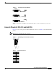
Figure 5 shows the wiring pattern for an E&M connector, and Table 2 lists the E&M pinouts.
Note The E&M VIC pinout depends on the PBX type and connection. Pins that are not used should not be
connected.
Figure 5 RJ-48S Wiring for E&M Connectors
Checking FXS VIC Installation
If you installed an FXS VIC, connect a handset to the VIC port. When router power is on, you should be
able to hear the dial tone when you lift the handset. The dial tone should stop after you dial a digit. If
you have trouble, use the show voice port command to make sure that the VIC is installed correctly, or
try connecting a different handset to the VIC.
2-Port ISDN BRI Card
The ISDN BRI NT/TE voice interface card provides a client-side (TE) ISDN S/T physical interface for
connection to an NT1 terminating an ISDN telephone network. It can also be configured to provide a
network termination (NT) interface with phantom power. Each of its two ports can carry two voice calls
(one over each ISDN B channel), for a total of four calls per ISDN BRI card.
Table 2 E&M Pinouts
Pin Signal Description
1 SB –48V signaling battery
2 M-lead Signaling input
3 R Ring, audio input
4 R or R1 Ring, audio input/output, or
output
5 T or T1 Tip, audio input/output, or
output
6 T Tip, audio input
7 E-lead Signaling output
8 SG Signaling ground return
H11421
1
8