CHAPT E R Getting Started This chapter contains information about safety, system specifications, inspecting the system, preventing electrostatic discharge (ESD) damage, and required tools and parts. For international regulatory compliance information, refer to the appendix “Regulatory Compliance.” If you plan to place the router on a desk or table, do not place anything on top of the router that weighs in excess of 10 pounds (4.5 kg). Excessive weight on top could damage the chassis.
Safety Recommendations Warning Before working on equipment that is connected to power lines, remove jewelry (including rings, necklaces, and watches). Metal objects will heat up when connected to power and ground and can cause serious burns or weld the metal object to the terminals. • Locate the emergency power-off switch for the room in which you are working. Then, if an electrical accident occurs, you can act quickly to shut off power.
System Specifications System Specifications Table 1-1 shows the specifications for the product. Table 1-1 System Specifications Description Design Specification Dimensions H x W x D 1.75"1 x 17.5" x 10.56" (4.44 cm x 44.45 cm x 26.82 cm) Weight 10 lb (4.5 kg) Input voltage, AC Power Supply Frequency Power dissipation 100 to 240 volts alternating current (VAC) 50 to 60 hertz (Hz) 40W (max.) 135.
System Specifications Description Design Specification Ethernet interface Attachment unit interface (AUI) IEEE 802.3 (DB-15) Hub interface 8, 14, or 16 RJ-45 (10BaseT) Token Ring interface IEEE 802.5 (DB-9), 8 or 16 RJ-45 Synchronous serial interfaces EIA/TIA-2322, EIA/TIA-449, V.35, X.21 (NRZ/NRZI3 and DTE/DCE4) EIA-530 (NRZ/NRZI and DTE) All serial cables use a DB-60 chassis connector.
Inspecting the System Inspecting the System Do not unpack the system until you are prepared to install it. If the final installation site is not ready, keep the chassis in the shipping container to prevent accidental damage. When you have determined where you want the router installed, proceed with the unpacking. Check the packing list to ensure that you received the following items: • • • • • • • • Router 6-foot (1.
Tools and Parts Required ground. To properly guard against ESD damage and shocks, the wrist strap and cord must operate effectively. If no wrist strap is available, ground yourself by touching the metal part of the chassis. Caution For safety, periodically check the resistance value of the antistatic strap, which should be within the range of 1 and 10 megohm. Tools and Parts Required Following are the tools and parts required to install the router: • Small, 3/16-inch (0.
CHAPT E R 2 Installing the Hardware Follow these steps to install, configure, and connect your router: Step 1 Install the router hardware using the procedures described in this chapter. Refer to the appendix “Regulatory Compliance” if you are installing the router in the United Kingdom, Europe, or Italy. Step 2 After installing the hardware, refer to the appropriate software publication to configure the router.
Installing the Rubber Feet Installing the Rubber Feet This section explains how to install the rubber feet on the bottom of the chassis. If you want to rack-mount the chassis, skip this section and proceed with the next section, “Rack-Mounting the Chassis.” If you want to wall-mount the chassis, skip this section and proceed with the section “Wall-Mounting the Chassis” later in this chapter.
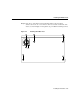
Installing the Rubber Feet Step 3 Peel off one of the rubber feet from the black adhesive strip and place it adhesive-side down onto one of the five round recessed areas on the back of the chassis, as shown in Figure 2-2. Repeat this step to install the remaining four feet.
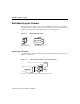
Rack-Mounting the Chassis Rack-Mounting the Chassis This section describes the procedures for rack-mounting the chassis. Your chassis ships with a bracket for use with a 19-inch rack or, if specified in your order, an optional, larger bracket for use with a 24-inch rack. The brackets are shown in Figure 2-3.
Rack-Mounting the Chassis Figure 2-5 24-Inch Rack Installation—Front Panel Forward H3893 SERIES Note: The second bracket attaches to the other side of the chassis. To install the chassis in a rack with the rear panel forward, attach the brackets as shown in Figure 2-6 or Figure 2-7. Figure 2-6 19-Inch Rack Installation—Rear Panel Forward Input: 100-240VAC Freq: 50.60 Hz Current: 1.2-0.6A Watts: 40W H1704 1 0 Note: The second bracket attaches to the other side of the chassis.
Rack-Mounting the Chassis To install the chassis in a center-mount telco rack, attach the brackets as shown in Figure 2-8 or Figure 2-9. Figure 2-8 Telco 19-Inch Rack Installation—Rear Panel Forward Input: 100-240VAC Freq: 50.60 Hz Current: 1.2-0.6A Watts: 40W H1705 1 0 Note: The second bracket attaches to the other side of the chassis. The brackets can also be installed with the front panel forward. Figure 2-9 Telco 24-Inch Rack Installation—Rear Panel Forward Input: 100-240VAC Freq: 50.
Rack-Mounting the Chassis Installing in a Rack After the brackets are secured to the chassis, you can rack-mount the chassis. Using the screws you provide, attach the chassis to the rack as shown in Figure 2-10 or Figure 2-11. Figure 2-10 Attaching the Chassis to the 19-Inch Rack—Rear Panel Forward Input: 100-240VAC Freq: 50.60 Hz Current: 1.2-0.6A Watts: 40W 1 H1719 0 Figure 2-11 Note: The second bracket attaches to the rack at the other side of the chassis.
Wall-Mounting the Chassis Wall-Mounting the Chassis Use the smaller brackets, for use with a 19-inch rack, to wall-mount chassis. The smaller brackets will provide the most stable position for the chassis. To wall-mount the chassis, follow these steps: Step 1 Attach the brackets as shown in Figure 2-12. Figure 2-12 Attaching the Wall-Mount Brackets Input: 100-240VAC Freq: 50/60 Hz Current: 1.2-0.
Wall-Mounting the Chassis Caution To prevent the chassis from pulling away from the wall when cables are attached, align the brackets and screws with a vertical wall stud. (See Figure 2-13.) To ensure adequate ventilation, make sure there is clearance between the router and the wall. Mount the router as shown in Figure 2-13, placing the chassis fan and power supply at the top.
Preparing for External Connections Preparing for External Connections Following are the procedures for making external connections to the different router, access server, and hub models.
Preparing for External Connections Figure 2-14 Model 2503 Rear Panel BRI CONSOLE AUX Protective grounding terminal Not telco compliant H1891 Telco compliant AUI SERIAL 0 SERIAL 1 BRI Input: 100-240VAC Freq: 50.60 Hz Current: 1.2-0.6A Watts: 40W CONSOLE AUX 1 0 CISCO 2503 1 2 3 4 5 6 7 Connections for Hub Models Figure 2-15 shows an example of the rear panel of a hub.
Preparing for External Connections Hub (Model 2516) Rear Panel H2826 Figure 2-15 1 2 3 4 5 6 7 8 Connections for Access Server Models Figure 2-16 shows the rear panel of an access server with 16 ports and the following connectors: 1 One or two 68-pin SCSI ports 2 Ethernet DB-15 or Token Ring DB-9 (models 2510 and 2512 not shown) 3 Synchronous serial DB-60 (2 connectors) 4 Console RJ-45 5 Auxiliary RJ-45 6 Protective grounding terminal (requires an M 3.
Preparing for External Connections Access Server (Model 2511) Rear Panel H2825 Figure 2-16 1 2 3 4 5 6 7 Making External Connections Following is the procedure for connecting external cables to the router. If your router has an Ethernet port, begin at Step 1. If it has a Token Ring port, begin at Step 3. If it is a hub model, begin at Step 4. Step 1 Connect the Ethernet port to a transceiver as shown in Figure 2-17. If necessary, extend the Ethernet cable as shown in Figure 2-18.
Preparing for External Connections Figure 2-17 Ethernet Cable Connections Ethernet transition cable (not supplied) Slide-latch connector Ethernet port DB-15 connector (with jackscrews) Rear Router (top view) Figure 2-18 H2046 Transceiver Extending the Cable from the Ethernet Port Ethernet transition cable (not supplied) Additional cable extension up to 164' (50 m) (not supplied) Transceiver H2047 Rear Router (top view) Step 3 Connect the Token Ring port to an MAU as shown in Figure 2-19.
Preparing for External Connections Token Ring Cable Connections Token Ring lobe cable (not supplied) Standard IEEE 802.5 connector Media attachment unit (MAU) Back H1904 Figure 2-19 DB-9 Token Ring port connector Router (top view) Step 4 Connect the serial ports to the modem or CSU/DSU as shown in Figure 2-20. Make certain to connect the 60-pin serial port connector as shown.
Preparing for External Connections Step 5 On hub models, connect RJ-45 cables from the Ethernet ports to your external Ethernet devices. If you have a router model go to Step 7, and if you have a access server, omit this step and continue with Step 6. Step 6 On access server models, connect modular SCSII-type breakout cables (available from Cisco Systems) to the 68-pin SCSI ports.
Preparing for External Connections Figure 2-21 RJ-45 Female Connector—BRI, Console, and Auxiliary Ports H1906 12345678 RJ-45 Warning Network hazardous voltages are accessible in the BRI cable. If you detach the BRI cable, detach the end away from the router first to avoid possible electric shock. Network hazardous voltages are also accessible on the system card in the area of the BRI port (RJ-45 connector), regardless of whether power is turned OFF. (See Figure 2-22.
Connecting the DC-Input Power Supply Caution To prevent damage to the system, make certain you connect the BRI cable to the BRI connector only and not to any other RJ-45 connector. The console, auxiliary, BRI, and hub ports all use RJ-45 connectors. Step 10 Using an M 3.5 thread-forming screw (not included), attach a ground wire to the protective grounding terminal on the chassis rear panel, as required by your installation. (See Figure 2-14.
Connecting the DC-Input Power Supply Wiring the DC-Input Power Supply If you ordered a Cisco 2500 series router with a DC-input power supply, follow the directions in this section for proper wiring. Figure 2-23 shows the rear of the DC-input power supply (Model 2501-DC). Warning Before conducting any of the following procedures, ensure that power is removed from the DC circuit.
Connecting the DC-Input Power Supply Step 2 Wire the DC-input power supply to the terminal block as shown in Figure 2-24. The proper wiring sequence is ground to ground, positive to positive, and negative to negative. Caution Do not overtorque the terminal block captive thumbscrew or terminal block contact screws. The recommended torque is 8.2 0.4 inch-lb. Caution Secure the wires so that they will not be disturbed by casual contact. For example, secure the wires to a rack frame using tie wraps.
Connecting the DC-Input Power Supply Figure 2-24 DC-Input Power Supply Connections Input: –40 – –72V Current: 1.5 –1.0A Watts: 40W Terminal block Ground Negative Positive H2679.
What to Do after Installing the Router Hardware What to Do after Installing the Router Hardware After you install the router hardware, the system is ready to be powered on and configured. For information on router software configuration, refer to the appropriate software publications. Note To order UniverCD, Cisco’s library of product information in CD-ROM format, or printed documentation, refer to Ordering Cisco Documentation, which is in your warranty pack.
3 CHAPT E R Reference This chapter contains information about troubleshooting, enabling booting from Flash memory, copying to Flash memory, and cable pinouts. For additional information about the Cisco 2500 series router hardware, refer to the Cisco 2500 Series Hardware Installation and Maintenance publication. Note The Cisco 2500 Series Hardware Installation and Maintenance publication is available on UniverCD or a printed copy can be ordered separately.
Troubleshooting • Does the system shut down after being ON a short time? — Suspect a thermal-induced shutdown. — Ensure that the chassis intake and exhaust vents are clear. — Suspect a power supply failure. The green OK LED (to the right of the AUX port) should be ON after the system initializes correctly. (See Figure 3-1.) Router LEDs—Rear-Panel View AUI SERIAL 0 (V2) SERIAL 1 (V2) BRI Input: 100-240VAC Freq: 50.60 Hz Current: 1.2-0.
Enabling Booting from Flash Memory Enabling Booting from Flash Memory To enable booting from Flash memory, set configuration register bits 3, 2, 1, and 0 to a value between 2 and 15 in conjunction with the boot system flash [filename] configuration command.
Copying to Flash Memory Following is a sample output for setting the configuration register to 0x2101, which tells the system to boot from ROM, but does not reset the break disable or check for a default netboot filename. router# configure terminal Enter configuration commands, one per line.
Cable Pinouts Following is a sample output for setting the configuration register to 0x2102, which tells the system to boot from ROM if netboot fails, disable break, and check for a default netboot filename. router(boot)# config term Enter configuration commands, one per line. Edit with DELETE, CTRL/W, and CTRL/U; end with CTRL/Z config-reg 0x2102 ^Z After copying the file (called IJ09140Z) to Flash memory from a TFTP server (called server1), the router is reloaded, as follows: router(boot)# reload ...
Cable Pinouts • • • • • • • • • EIA/TIA-232 DTE and DCE synchronous serial, Table 3-8 EIA/TIA-449 DTE and DCE synchronous serial, Table 3-9 V.35 DTE and DCE synchronous serial, Table 3-10 X.
Cable Pinouts Table 3-2 Auxiliary Port Pinouts (RJ-45) Pin1 Signal Input/Output 1 RTS Output 2 DTR Output 3 TXD Output 4 GND – 5 GND – 6 RXD Input 7 CD Input 8 CTS Input 1. Any pin not referenced is not connected. The connection of pins between the RJ-45 connector and the end device depends on the type of cable and adapter used. Either a straight or rolled cable can be used. Refer to Table 3-3 for the pinout of a straight and a rolled cable.
Cable Pinouts Table 3-3 RJ-45 Straight and Rolled Cables RJ-45 Pins Straight Cable Pinout Rolled Cable Pinout 1 1 8 2 2 7 3 3 6 4 4 5 5 5 4 6 6 3 7 7 2 8 8 1 Table 3-4 Pins for the RJ-45, MDTE/FDTE, MDCE/FDCE, and MMOD Cable DB-25 Adapters RJ-45 Pins MDTE/FDTE Pins1 MDCE/FDCE Pins MMOD Pins2 1 4 5 5 2 20 6 8 3 2 3 3 4 7 7 7 5 7 7 7 6 3 2 2 7 6 20 20 8 5 4 4 1. The FDTE adapter that is available through Cisco is labeled “Terminal.” 2.
Cable Pinouts Table 3-5 Connection Configuration Cisco 2500 Port RJ-45 Cable Type DB-25 Adapter End Device Console Rolled MDTE/FDTE Terminal Console Straight MDCE/FDCE Terminal Console Rolled MMOD Modem Aux Rolled MDTE/FDTE Terminal Aux Straight MDCE/FDCE Terminal Aux Rolled MMOD Modem 1 1. Connecting a modem to the console port is not recommended. The console port does not have modem or flow control.
Cable Pinouts Table 3-6 BRI Port Pinout (RJ-45) 8 Pin1 TE2 NT3 Polarity 3 Transmit Receive + 4 Receive Transmit + 5 Receive Transmit – 6 Transmit Receive – 1. Pins 1, 2, 7, and 8 are not used. 2. TE refers to terminal terminating layer 1 aspects of TE1, TA, and NT2 functional groups. 3. NT refers to network terminating layer 1 aspects of NT1 and NT2 functional groups. Warning Network hazardous voltages are accessible in the BRI cable.
Cable Pinouts Table 3-7 EIA-530 DTE Serial Cable Pinout (DB-25) 25 Pin1 Signal Direction DTE DCE2 25 Pin Signal Direction DTE DCE J2-1 – Shield – – – J2-8 J2-10 CF(A), DCD+ CF(B), DCD– <— <— J2-2 J2-14 BA(A), TxD+ BA(B), TxD– —> —> J2-15 J2-12 DB(A), TxC+ DB(B), TxC– <— <— J2-3 J2-16 BB(A), RxD+ BB(B), RxD– <— <— J2-17 J2-9 DD(A), RxC+ DD(B), RxC– <— <— J2-4 J2-19 CA(A), RTS+ CA(B), RTS– —> —> J2-18 J2-7 LL Circuit GND —> – J2-5 J2-13 CB(A), CTS+ CB(B), CTS– <— <— J2-20 J
Cable Pinouts Table 3-8 EIA/TIA-232 DTE and DCE Serial Cable Pinouts (DB-25) 25 Pin1 Signal Direction DTE DCE 25 Pin Signal Direction DTE DCE J2-1 Shield GND _ J2-7 Shield Circuit GND – – – J2-2 Shield TxD – —> – J2-8 Shield DCD – <— – J2-3 Shield RxD – <— – J2-15 Shield TxC – <— – J2-4 Shield RTS – —> – J2-17 Shield RxC – <— – J2-5 Shield CTS – <— – J2-18 Shield LTST – —> – J2-6 Shield DSR – <— – J2-20 Shield DTR – —> – J2-24 Shield TxCE – —> – 1.
Cable Pinouts Table 3-9 EIA/TIA-449 DTE and DCE Serial Cable Pinouts (DB-37) 37 Pin1 Signal Direction DTE DCE J2-1 Shield GND J2-4 J2-22 37 Pin Signal Direction DTE DCE – J2-9 J2-27 CS+ CS– —> —> SD+ SD– <— <— J2-10 J2-37 LL SC —> – J2-5 J2-23 ST+ ST– —> —> J2-11 J2-29 DM+ DM– —> —> J2-6 J2-24 RD+ RD– —> —> J2-12 J2-30 TR+ TR– <— <— J2-7 J2-25 RS+ RS– <— <— J2-13 J2-31 RR+ RR– —> —> J2-8 J2-26 RT+ RT– —> —> J2-17 J2-35 TT+ TT– <— <— J2-19 J2-20 SG RC – – 1.
Cable Pinouts Table 3-10 V.
Cable Pinouts Table 3-11 X.21 DTE and DCE Serial Cable Pinouts (DB-15) 15 Pin1 Signal Direction DTE DCE J2-1 Shield GND – J2-2 J2-9 Transmit+ Transmit– —> —> J2-3 J2-10 Control+ Control– —> —> J2-4 J2-11 Receive+ Receive– <— <— J2-5 J2-12 Indication+ Indication– <— <— J2-6 J2-13 Timing+ Timing– <— <— J2-8 Shield Circuit GND – – – 1. Any pin not referenced is not connected.
Cable Pinouts Table 3-12 Ethernet (AUI) Port Pinout (DB-15) 15 Pin Ethernet Circuit Signal 1 CI-S Control In Circuit Shield 2 CI-A Control In Circuit A 3 DO-A Data Out Circuit A 4 DI-S Data In Circuit Shield 5 DI-A Data In Circuit A 6 VC Voltage Common 7 CO-A Control Out Circuit A (not connected) 8 CO-S Control Out Circuit Shield (not connected) 9 CI-B Control In Circuit B 10 DO-B Data Out Circuit B 11 DO-S Data Out Circuit Shield 12 DI-B Data In Circuit B 13 VP V
Cable Pinouts Table 3-13 Pin Signal 1 TX+ 2 TX– 3 RX+ 4 – 5 – 6 RX– 7 – 8 – Table 3-14 Ethernet 10BaseT Port Pinout (RJ-45) Token Ring Port Pinout (DB-9) 9 Pin1 Signal 1 Receive R1– 3 +5V2 5 Transmit O5– 6 Receive G6+ 9 Transmit B9+ 1. Pins 2, 4, 7, and 8 are ground. 2. 600 mA maximum.
Cable Pinouts Table 3-15 Asynchronous Breakout Cable Pinout (8-Pin RJ-45) 8-Pin RJ-45 Signal Direction 1 CTS <— 2 DSR/DCD <— 3 RXD <— 4 RXD/GND - 5 TXD/GND - 6 TXD —> 7 DTR —> 8 RTS —> 3-18 Cisco 2500 Series Hardware Installation
Cable Pinouts Table 3-16 Asynchronous-Line Cable Pinout (68-Pin SCSI) RJ-45 Plug Pin Signal 68-Pin SCSI (J1) 1 8 RTS 2 7 DTR 36 6 TXD 3 5 TXD GND 37 4 RXD GND 4 3 RXD 38 2 DSR 5 1 CTS 39 8 RTS 6 7 DTR 40 6 TXD 7 5 TXD GND 41 4 RXD GND 8 3 RXD 42 2 DSR 9 1 CTS 43 8 RTS 10 7 DTR 44 6 TXD 11 5 TXD GND 45 4 RXD GND 12 3 RXD 46 2 DSR 13 1 CTS 47 2 3 Reference 3-19
Cable Pinouts RJ-45 Plug Pin Signal 68-Pin SCSI (J1) 4 8 RTS 14 7 DTR 48 6 TXD 15 5 TXD GND 49 4 RXD GND 16 3 RXD 50 2 DSR 17 1 CTS 51 8 RTS 18 7 DTR 52 6 TXD 19 5 TXD GND 53 4 RXD GND 20 3 RXD 54 2 DSR 21 1 CTS 55 8 RTS 22 7 DTR 56 6 TXD 23 5 TXD GND 57 4 RXD GND 24 3 RXD 58 2 DSR 25 1 CTS 59 5 6 3-20 Cisco 2500 Series Hardware Installation
Cable Pinouts RJ-45 Plug Pin Signal 68-Pin SCSI (J1) 7 8 RTS 26 7 DTR 60 6 TXD 27 5 TXD GND 61 4 RXD GND 28 3 RXD 62 2 DSR 29 1 CTS 63 8 RTS 30 7 DTR 64 6 TXD 31 5 TXD GND 65 4 RXD GND 32 3 RXD 66 2 DSR 33 1 CTS 67 8 Reference 3-21
Cable Pinouts Figure 3-3 shows the DB-25 breakout cable with pinouts for the 68-pin SCSI port and the DB-25 port. Table 3-17 lists the pinouts for the DB-25 end, and Table 3-18 lists the pinouts for the 68-pin SCSI connector end. Figure 3-3 Asynchronous Serial Interface Breakout Cable Assembly (68-Pin SCSI-to-DB-25) DB-25 connector Pin 68 J2-13 J2-25 SCSI 68-pin connector Pin 34 J2-14 J2-1 DB-25 connectors are located at the end of all eight cables.
Cable Pinouts Table 3-17 Asynchronous Breakout Cable Pinouts (DB-25) DB-25 Plug1 Signal Direction 4 RTS —> 20 DTR —> 2 TXD —> 7 TXD GND — 7 RXD GND — 3 RXD <— 8 DSR <— 5 CTS <— 1. Any pin not referenced is not connected.
Cable Pinouts DB-25 Plug Pin Signal 68-Pin SCSI (J1) 2 4 RTS 6 20 DTR 40 2 TXD 7 7 TXD GND 41 7 RXD GND 8 3 RXD 42 8 DSR 9 5 CTS 43 4 RTS 10 20 DTR 44 2 TXD 11 7 TXD GND 45 7 RXD GND 12 3 RXD 46 8 DSR 13 5 CTS 47 4 RTS 14 20 DTR 48 2 TXD 15 7 TXD GND 49 7 RXD GND 16 3 RXD 50 8 DSR 17 5 CTS 51 3 4 3-24 Cisco 2500 Series Hardware Installation
Cable Pinouts DB-25 Plug Pin Signal 68-Pin SCSI (J1) 5 4 RTS 18 20 DTR 52 2 TXD 19 7 TXD GND 53 7 RXD GND 20 3 RXD 54 8 DSR 21 5 CTS 55 4 RTS 22 20 DTR 56 2 TXD 23 7 TXD GND 57 7 RXD GND 24 3 RXD 58 8 DSR 25 5 CTS 59 4 RTS 26 20 DTR 60 2 TXD 27 7 TXD GND 61 7 RXD GND 28 3 RXD 62 8 DSR 29 5 CTS 63 6 7 Reference 3-25
Cable Pinouts DB-25 Plug Pin Signal 68-Pin SCSI (J1) 8 4 RTS 30 20 DTR 64 2 TXD 31 7 TXD GND 65 7 RXD GND 32 3 RXD 66 8 DSR 33 5 CTS 67 3-26 Cisco 2500 Series Hardware Installation
APPEND IX A Regulatory Compliance This appendix contains information for customers installing systems in the United Kingdom, Europe, and Italy. Refer to the section about your location. Information for United Kingdom Use Only Cisco Systems declaration of operating conditions: The Cisco 2500 Series is designed to meet the requirements of NET1 and NET2.
Information for European Community Use Only Connection of Power Supply. The Gateway Server is intended for use when supplied with power from a supply providing 220-240 VAC, 50/60 Hz up to 5 Amps. Other usage will invalidate any approval given to this apparatus if as a result it ceases to comply with BS6301: 1989. The Cisco 2500 Series is brought into service by the supplier. Information for European Community Use Only The ports marked “Ethernet,” “Token Ring,” “Console,” and “AUX” are SELV circuits.
APPEND IX B System Specifications Following are the specifications for the router system: Table B-1 System Specifications Description Design Specification Dimensions H x W x D 1.75"1 x 17.5" x 10.56" (4.44 cm x 44.45 cm x 26.82 cm) Weight 10 lb (4.5 kg) Input voltage, frequency, and power dissipation 100 to 240 volts alternating current (VAC) at 50 to 60 hertz (Hz) 40W (max.) 135.
Description Design Specification Hub Network interface options 1 Ethernet, 2 synchronous serial, 8 hub (2505) 1 Token Ring, 2 synchronous serial, 8 hub (2506) 1 Ethernet, 2 synchronous serial, 16 hub (2507)1 Token Ring, 2 synchronous serial, 16 hub (2508) Access Server Network interface options 1 Ethernet, 2 synchronous serial, 8 asynchronous serial (2509) 1 Token Ring, 2 synchronous serial, 8 asynchronous serial (2510) 1 Ethernet, 2 synchronous serial, 16 asynchronous serial (2511) 1 Token Ring, 2 syn