
Specifications

2-12 Cisco 2500 Series Hardware Installation
Preparing for External Connections
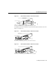
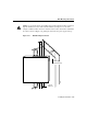
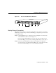
Figure 2-15 Hub (Model 2516) Rear Panel
Connections for Access Server Models
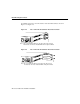
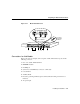
Figure 2-16 shows the rear panel of an access server with 16 ports and the following
connectors:
1 One or two 68-pin SCSI ports
2 Ethernet DB-15 or Token Ring DB-9 (models 2510 and 2512 not shown)
3 Synchronous serial DB-60 (2 connectors)
4 Console RJ-45
5 Auxiliary RJ-45
6 Protective grounding terminal (requires an M 3.5 thread-forming screw that is not
included)
7 AC power input
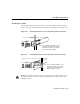
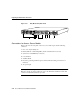
Note If you are installing a model 2501, 2503, 2509, 2511, 2513, or 2514 and your
Ethernet connection requires jackscrews, remove the slide-latch assembly from the AUI
connector and attach the jackscrews provided.
4
21
78
H2826
3
56