
Specifications


Installing the Hardware 2-19
Connecting the DC-Input Power Supply
Wiring the DC-Input Power Supply
If you ordered a Cisco 2500 series router with a DC-input power supply, follow the
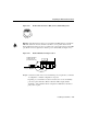
directions in this section for proper wiring. Figure 2-23 shows the rear of the DC-input
power supply (Model 2501-DC).
Warning Before conducting any of the following procedures, ensure that power is
removed from the DC circuit. To ensure that all power is OFF, locate the circuit breaker on
the panel board that services the DC circuit, switch the circuit breaker to the OFF position,
and tape the switch handle of the circuit breaker in the OFF position.
Note The installation must comply with all applicable codes.
Note This product is intended for installation in restricted access areas and is approved for
use with copper conductors only.
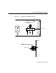
Figure 2-23 Cisco 2500 Series DC-Input Power Supply—Rear View
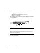
Figure 2-24 shows the Cisco 2500 DC-input power supply terminal block. Follow these
procedures for wiring the terminal block.
Step 1 Attach the appropriate lugs at the wire end of the power supply cord.
H2678