About This Guide This section discusses the objectives, audience, organization, and conventions of the Cisco 2524 and Cisco 2525 Router User Guide. All Cisco technical documentation and additional literature are available on UniverCD, Cisco’s online library of product information. UniverCD is updated and shipped monthly, so it might be more up to date than printed documentation. UniverCD is available both as a single CD and as an annual subscription.
Document Organization Document Organization The major sections of this user guide are as follows: • Chapter 1, “Overview of the Cisco 2524 and Cisco 2525 Routers,” discusses the features and specifications of the routers. • Chapter 2, “Preparing to Install the Cisco 2524 and Cisco 2525 Routers,” discusses environmental requirements and preparation for network connections, and describes the various ports and how to prepare for connections between networks and ports.
Document Conventions Document Conventions This publication uses the following conventions to convey instructions and information. Command descriptions use these conventions: • • • • Commands and keywords are in boldface font. Variables for which you supply values are in italic font. Elements in square brackets ([ ]) are optional. Alternative but required keywords are grouped in braces ({ }) and are separated by vertical bars ( | ).
Document Conventions Warning This warning symbol means danger. You are in a situation that could cause bodily injury. Before you work on any equipment, you must be aware of the hazards involved with electrical circuitry and familiar with standard practices for preventing accidents. (To see translated versions of this warning, refer to the appendix “Translated Safety Warnings.
1 CHAPT E R Overview of the Cisco 2524 and Cisco 2525 Routers The Cisco 2524 and Cisco 2525 routers provide LAN and WAN access in a low-cost modular router platform that can grow with your internetworking needs. The Cisco 2524 offers an Ethernet (attachment unit interface [AUI] or 10BaseT) LAN connection, and the Cisco 2525 offers a Token Ring (shielded twisted-pair [STP] or unshielded twisted-pair [UTP]) LAN connection.
Features The ISDN WAN modules are designed so that you cannot insert them into the synchronous serial WAN slots. A blank slot cover is installed over unused slots.
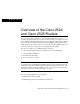
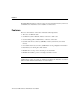
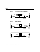
Features Figure 1-1 shows the front panel, which is the same for both routers. Cisco 2524 and Cisco 2525 Front Panel H1690 Figure 1-1 Figure 1-2 shows the rear panel of the Cisco 2524 router, and Figure 1-3 shows the rear panel of the Cisco 2525 router.
Features SERIAL 0 SERIAL 1 Cisco 2525 Rear Panel H5271 Figure 1-3 BRI 0 Token Ring LAN Console port (DB-9) activity port LED (RJ-45) Token Ring Auxiliary in-ring LED UTP port port (RJ-45) (RJ-45) On/off switch Power Figure 1-4 through Figure 1-9 show the WAN modules. Figure 1-10 shows the blank slot cover.
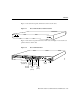
Features Figure 1-5 4-Wire 56/64-kbps DSU/CSU WAN Module Transmit LED 4-WIRE 56K/64K DSU/CSU Captive screw CD RJ-48S Figure 1-6 TX LB RX AL Carrier Alarm LED detect LED Receive LED H5047 Loopback LED Captive screw Fractional T1/T1 DSU/CSU WAN Module Transmit LED MON JACK IN OUT FTI/TI DSU/CSU Captive screw CD Monitor jack TX LB RX AL NET RJ-48C Carrier Alarm LED detect LED Receive LED H5048 Loopback LED Captive screw Overview of the Cisco 2524 and Cisco 2525 Routers 1-5
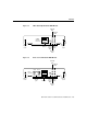
Features Figure 1-7 Five-in-One Synchronous Serial WAN Module SERIAL H5049 ACTIVITY Captive screw Figure 1-8 DB-60 Serial activity LED Captive screw ISDN BRI WAN Module ACTIVITY S/T Captive screw Captive screw ISDN BRI with Integrated NT1 WAN Module ACT ISDN-BRI with NTI U Captive screw ISDN BRI activity LED RJ-45 1-6 Cisco 2524 and Cisco 2525 Router User Guide NTI H5051 Figure 1-9 RJ-45 H5050 ISDN-BRI Captive screw
Specifications Figure 1-10 Blank Slot Cover H5052 BLANK Do not plug/unplug modules with power on. Captive screw Captive screw Specifications The specifications of the Cisco 2524 and Cisco 2525 routers are listed in Table 1-1. Table 1-1 System Specifications Description Specification Dimensions (H x W x D) 1.75 x 17.5 x 10.56" one rack unit (4.44 x 44.45 x 26.82 cm) Weight 10 lb (4.5 kg) Input voltage, AC power supply Current Frequency Power dissipation 100–240 VAC1 1.2–0.
Specifications Description Specification WAN interface options • 2-wire switched 56-kbps DSU/CSU (RJ-11) • 4-wire 56/64-DSU/CSU (RJ-48S) • Fractional T1/T1 DSU/CSU (RJ-48C) • Five-in-one synchronous serial (DB-60) • ISDN BRI (RJ-45) • ISDN BRI with integrated NT1 (RJ-45) LAN interface options Cisco 2524: Ethernet AUI (DB-15) or 10BaseT (RJ-45) Cisco 2525: Token Ring STP (DB-9) or UTP (RJ-45) Synchronous serial interfaces (five-in-one synchronous serial WAN module) • EIA/TIA-232, EIA/TIA-449, V.
FCC Part 68 FCC Part 68 The following text is required for FCC Part 68 regulatory compliance: The equipment complies with Part 68 of the FCC rules. On the bottom of the equipment is a label that shows the FCC registration number. If the equipment causes harm to the telephone network, the telephone company may temporarily discontinue service. If possible, advance notification is given; otherwise, notification is given as soon as possible.
FCC Part 68 Table 1-2 Information About Leased-Line Facilities Module Type Service Type Digital Facility Interface Code Service Order Code Network Jack 4-Wire 56/64-kbps DSU/CSU WAN Module 2.4-kbps digital interface 04DU5-24 6.0F RJ-48S 4.8-kbps digital interface 04DU5-48 6.0F RJ-48S 9.6-kbps digital interface 04DU5-96 6.0F RJ-48S 19.2-kbps digital interface 04DU5-19 6.0F RJ-48S 38.4-kbps digital interface 04DU5-38 6.0F RJ-48S 56-kbps digital interface 04DU5-56 6.
2 CHAPT E R Preparing to Install the Cisco 2524 and Cisco 2525 Routers This chapter describes the tasks you must perform before you begin to install the Cisco 2524 and Cisco 2525 routers, and includes the following sections: • • • • • • Safety Recommendations General Site Requirements Installation Checklist Creating a Site Log Preparing to Connect to a Network Inspecting the System Safety Recommendations Follow these guidelines to ensure general safety: • • • • Keep the chassis area clear and dust-fr
Safety Recommendations Warning Ultimate disposal of this product should be handled according to all national laws and regulations. (To see translated versions of this warning, refer to the appendix “Translated Safety Warnings.”) Maintaining Safety with Electricity Follow these guidelines when working on equipment powered by electricity. Warning Before working on equipment that is connected to power lines, remove jewelry (including rings, necklaces, and watches).
Safety Recommendations Warning Read the installation instructions before you connect the system to its power source. (To see translated versions of this warning, refer to the appendix “Translated Safety Warnings.”) • Look carefully for possible hazards in your work area, such as moist floors, ungrounded power extension cables, frayed power cords, and missing safety grounds. • If an electrical accident occurs, proceed as follows: — Use caution; do not become a victim yourself.
General Site Requirements General Site Requirements This section describes the requirements your site must meet for safe installation and operation of your system. Ensure that your site is properly prepared before beginning installation. Site Environment The routers can be placed on a desktop or mounted in a rack or on a wall. The location of the routers and the layout of your equipment rack or wiring room are extremely important for proper system operation.
General Site Requirements Configuring Equipment Racks The following tips will help you plan an acceptable equipment rack configuration: • Enclosed racks must have adequate ventilation. Ensure that the rack is not overly congested because each unit generates heat. An enclosed rack should have louvered sides and a fan to provide cooling air. • When mounting a chassis in an open rack, ensure that the rack frame does not block the intake or exhaust ports.
Installation Checklist The router’s AC power supply includes the following features: • • Autoselects either 110V or 220V operation. All units include a 6-foot (1.8-meter) electrical power cord. (A label near the power cord indicates the correct voltage, frequency, current draw, and power dissipation for the unit.) Warning This product relies on the building’s installation for short-circuit (overcurrent) protection. Ensure that a fuse or circuit breaker no larger than 120 VAC, 15A U.S.
Installation Checklist Installation checklist for site______________________________________________ Router name__________________________________________________________ Task Verified by Date Installation checklist copied Background information placed in Site Log Site power voltages verified Required tools available Additional equipment available Router received Optional UniverCD or printed documentation received Chassis components verified Initial electrical connections established ASCII terminal or
Creating a Site Log Creating a Site Log The Site Log provides a record of all actions relevant to the router. Keep it near the chassis where anyone who installs or maintains the router has access to it. Use the Installation Checklist (see the previous section, “Installation Checklist”) to verify steps in the installation and maintenance of your router. Site Log entries might include the following: • Installation progress—Make a copy of the Installation Checklist and insert it into the Site Log.
Preparing to Connect to a Network 2-Wire Switched 56-kbps DSU/CSU WAN Module The 2-wire switched 56-kbps DSU/CSU WAN module includes an RJ-11 port for connection to a WAN. Cables are not included with the modules; however, port pinouts are listed in the section “Fractional T1/T1 DSU/CSU Module Port Pinouts” in the appendix “Cabling Specifications for the Cisco 2524 and Cisco 2525 Routers.” Warning Network hazardous voltages are present in the BRI, fractional T1/T1, and switched 56 cables.
Preparing to Connect to a Network 4-Wire 56/64-kbps DSU/CSU WAN Module The 4-wire 56/64-kbps DSU/CSU WAN module includes an RJ-48S port for connection to a WAN. Cables are not included with the module; however, port pinouts are listed in the section “4-Wire 56/64-kbps DSU/CSU Module Port Pinouts” in the appendix “Cabling Specifications for the Cisco 2524 and Cisco 2525 Routers. Warning Network hazardous voltages are present in the BRI, fractional T1/T1, and switched 56 cables.
Preparing to Connect to a Network Table 2-2 4-Wire 56/64-kbps DSU/CSU Module Network Specifications Description Specification Loop rates DDS1: 2.4, 4.8, 9.6, 19.2, 38.4, 56, and 64 kbps Switched 56: 56 kbps Data rates 2.4, 4.8, 9.6, 19.2, 56, and 64 kbps Line requirements DDS: AT&T Publication 62310 Switched 56: AT&T Publication 41458, Sprint TS-0046 Receiver sensitivity –45 dB at all loop rates 1. DDS = digital data system (leased or dedicated lines).
Preparing to Connect to a Network Table 2-3 Fractional T1/T1 DSU/CSU WAN Module Network Specifications Description Specification Line rate 1.544 Mbps1 Data rates n x 56 or n x 64 kbps, where n = 1 to 242 Standards AT&T Publication 62411, 54016, and 43801 1. Mbps = megabits per second. 2. The T1 interface is not channelized. ISDN Connections Use an appropriate cable (not included) to connect the router directly to an ISDN. (See Table 2-4.
Preparing to Connect to a Network Table 2-4 ISDN BRI Cable Specifications Specification High-Capacitance Cable Low-Capacitance Cable Resistance (at 96 kHz) 160 ohms/km 160 ohms/km Capacitance (at 1 kHz) 1 120 nF /km 30 nF/km Impedance (96 kHz) 75 ohms 150 ohms Wire diameter 0.024" (0.6 mm) 0.024" (0.6 mm) Distance limitation 32.8' (10 m) 32.8' (10 m) 1. nF = nanoFarad.
Preparing to Connect to a Network Table 2-5 EIA/TIA-232 Speed and Distance Limitations Data Rate (Baud) Distance (Feet) Distance (Meters) 2400 200 60 4800 100 30 9600 50 15 19200 50 15 38400 50 15 57600 25 7.6 115200 12 3.7 The use of balanced drivers allows EIA/TIA-449 signals to travel greater distances than the EIA/TIA-232 standard. Table 2-6 lists the standard relationship between baud rate and maximum distance for EIA/TIA-449 signals. These limits are also valid for V.
Preparing to Connect to a Network Ethernet Connections On the Cisco 2524 router, there are two Ethernet ports, an AUI port and a 10BaseT port, on the rear panel of the router. To connect your router to an Ethernet network, you can use either the Ethernet AUI or 10BaseT port, but not both. The router automatically detects which port is in use. (If you attempt to use both ports, only the 10BaseT port will work.
Preparing to Connect to a Network The main difference between the console and auxiliary ports is that the auxiliary port supports flow control and the console port does not. Flow control paces the transmission of data between a sending device and a receiving device. Flow control ensures that the receiving device can absorb the data sent to it before the sending device sends more.
Inspecting the System Inspecting the System Do not unpack the router until you are ready to install it. If the final installation site will not be ready for some time, keep the chassis in its shipping container to prevent accidental damage. When you have determined where you want the router installed, proceed with unpacking it. The router, cables, UniverCD or printed publications, and any optional equipment you ordered might be shipped in more than one container.
Inspecting the System 2-18 Cisco 2524 and Cisco 2525 Router User Guide
3 CHAPT E R Installing the Cisco 2524 and Cisco 2525 Routers This chapter guides you through the installation of the Cisco 2524 and Cisco 2525 routers and includes the following sections: • • • • • • Required Tools and Parts Setting Up the Chassis Connecting the DC Power Supply Connecting to the Network Connecting the Console Terminal and Modem What to Do after Installing the Router Hardware Warning Only trained and qualified personnel should be allowed to install or replace this equipment.
Required Tools and Parts Required Tools and Parts Following are the tools and parts required to install the router: • • • Flat-blade screwdrivers: small, 3/16-inch (0.476 cm) and medium, 1/4-inch (0.
Setting Up the Chassis Setting Up the Chassis You can set the chassis on a desktop, install it in a rack, or mount it on a wall or other flat surface. Use the procedure in this section that best fits the needs of your network. Setting the Chassis on a Desktop Before setting the router on a desktop, shelf, or other flat, secure surface, perform the following steps to install the rubber feet: Step 1 Locate the rubber feet on the black adhesive strip that shipped with the chassis. (See Figure 3-1.
Setting Up the Chassis Figure 3-2 Installing the Rubber Feet H4795 Fan Step 4 Place the router right-side up on a flat, smooth, secure surface. Do not place anything on top of the router that weighs more than 10 pounds (4.5 kg). Excessive weight on top could damage the chassis. Caution Rack-Mounting the Chassis This section describes the procedures for rack-mounting the chassis.
Setting Up the Chassis Identifying the Brackets Bracket for use with a 19-inch rack Bracket for use with a 24-inch rack H4201 Figure 3-3 Attaching the Brackets To install the chassis in a rack with the front panel forward, attach the brackets as shown in Figure 3-4 or Figure 3-5. 19-Inch Bracket Installation—Front Panel Forward SERIES H1706 Figure 3-4 Note: The second bracket attaches to the other side of the chassis.
Setting Up the Chassis To install the chassis in a rack with the rear panel forward, attach the brackets as shown in Figure 3-6 or Figure 3-7. Figure 3-6 19-Inch Bracket Installation—Rear Panel Forward Input: 100-240VAC Freq: 50.60 Hz Current: 1.2-0.6A Watts: 40W H1704 1 0 Note: The second bracket attaches to the other side of the chassis. Figure 3-7 24-Inch Bracket Installation—Rear Panel Forward Input: 100-240VAC Freq: 50.60 Hz Current: 1.2-0.
Setting Up the Chassis To install the chassis in a center-mount telco rack, attach the brackets as shown in Figure 3-8 or Figure 3-9. Figure 3-8 Telco 19-Inch Bracket Installation—Rear Panel Forward Input: 100-240VAC Freq: 50.60 Hz Current: 1.2-0.6A Watts: 40W H1705 1 0 Note: The second bracket attaches to the other side of the chassis. The brackets can also be installed with the front panel forward. Figure 3-9 Telco 24-Inch Bracket Installation—Rear Panel Forward Input: 100-240VAC Freq: 50.
Setting Up the Chassis Installing in a Rack After the brackets are secured to the chassis, you can rack-mount the chassis. Using the screws you provide, attach the chassis to the rack as shown in Figure 3-10 or Figure 3-11. Figure 3-10 Attaching the Chassis to the 19-Inch Rack—Rear Panel Forward Input: 100-240VAC Freq: 50.60 Hz Current: 1.2-0.6A Watts: 40W 1 H1719 0 Figure 3-11 Note: The second bracket attaches to the rack at the other side of the chassis.
Setting Up the Chassis Wall-Mounting the Chassis Use the smaller brackets (for use with a 19-inch rack) to wall-mount the chassis. The smaller brackets provide the most stable position for the chassis. Take the following steps to wall-mount the chassis: Step 1 Attach the brackets as shown in Figure 3-12. Figure 3-12 Attaching the Wall-Mount Brackets Input: 100-240VAC Freq: 50/60 Hz Current: 1.2-0.
Setting Up the Chassis Wall-Mounting the Chassis H5367 SERIAL 0 SERIAL 1 BRI 0 Figure 3-13 3-10 Cisco 2524 and Cisco 2525 Router User Guide
Connecting the DC Power Supply Connecting the DC Power Supply The Cisco 2524 router offers an optional direct current (DC) power supply (not available with the Cisco 2525 router). This section describes the DC power supply specifications and wiring. Warning This unit is intended for installation in restricted access areas. (To see translated versions of the warning, refer to the appendix “Translated Safety Warnings.
Connecting the DC Power Supply Wiring the DC Power Supply If you ordered a Cisco 2524 router with a DC power supply, follow the directions in this section to wire the terminal block. Warning Before performing any of the following procedures, ensure that power is removed from the DC circuit.
Connecting the DC Power Supply Figure 3-14 DC Power Supply Connections Input: –40– –72V Current: 1.5 –1.
Connecting to the Network Warning When stranded wiring is required, use approved wiring terminations, such as closed-loop or spade-type with upturned lugs. These terminations should be the appropriate size for the wires and should clamp both the insulation and conductor. (To see translated versions of this warning, refer to the appendix “Translated Safety Warnings.”) Caution Do not overtorque the terminal block captive thumbscrew or terminal block contact screws. The recommended torque is 8.2 0.
Connecting to the Network You can connect the router to your Ethernet network in one of the following ways: • Use an Ethernet AUI cable to connect the Ethernet AUI port to an Ethernet transceiver. (See Figure 3-15.) • Use a straight-through 10BaseT cable to connect the 10BaseT port to a 10BaseT hub. (See Figure 3-16.) • Use a crossover 10BaseT cable to connect the 10BaseT port to a PC network interface card. (See Figure 3-17.
Connecting to the Network Connecting to a 10BaseT Hub H5494 Figure 3-16 SERIAL 0 SERIAL 1 BRI 0 Router Ethernet 10BaseT port (RJ-45) 10BaseT hub AUI 8 7 1 Straight-through 10BaseT cable 3-16 Cisco 2524 and Cisco 2525 Router User Guide
Connecting to the Network Figure 3-17 BRI 0 Router Ethernet 10BaseT port (RJ-45) PC OK ETH Crossover 10BaseT cable Network interface card LAN H5370 SERIAL 1 SER 0 SERIAL 0 Connecting to a PC Network Interface Card Installing the Cisco 2524 and Cisco 2525 Routers 3-17
Connecting to the Network Connecting to a Token Ring Network If you have a Cisco 2524 router, you can connect the router to your Token Ring network in one of the following ways: • Use a shielded Token Ring lobe cable to connect the Token Ring port (DB-9) to a media attachment unit (MAU). To ensure agency compliance with electromagnetic emissions requirements (EMI), make sure the cable is shielded. (See Figure 3-18.) • Use a twisted-pair cable to connect the Token Ring port (RJ-45) to a Token Ring hub.
Connecting to the Network Connecting to a Token Ring Hub H5949 Figure 3-19 SERIAL 0 SERIAL 1 BRI 0 Router Token Ring port (RJ-45) Token Ring hub DB-9 8 7 1 UTP cable Connecting to a WAN Although the illustrations in this section show the Cisco 2524 router, the procedures are the same for both the Cisco 2524 and Cisco 2525 routers. Warning Do not work on the system or connect or disconnect cables during periods of lightning activity.
Connecting to the Network Take the following steps to connect the router to your WAN: Step 1 If you have a 2-wire switched 56-kbps module, use a straight-through RJ-11-to-RJ-11 cable to connect the RJ-11 port to an RJ-11 jack. (See Figure 3-20.
Connecting to the Network Step 2 If you have a 4-wire 56/64-kbps DSU/CSU module, use a straight-through RJ-48S-to-RJ-48S cable to connect the RJ-48S port to an RJ-48S jack. (See Figure 3-21.
Connecting to the Network Step 3 If you have a fractional T1/T1 DSU/CSU module, use a straight-through RJ-48C-to-RJ-48C cable to connect the RJ-48C port to an RJ-48C jack. (See Figure 3-22.
Connecting to the Network Step 4 If you have a synchronous serial module, use a serial transition cable to connect the synchronous serial port to a modem or DSU/CSU. (See Figure 3-23.) Connecting Synchronous Serial Cables H5369 Figure 3-23 SERIAL ACTIVITY SERIAL 0 Serial transition cable SERIAL 1 Synchronous serial port (DB-60) BRI 0 Router DSU/CSU or other DCE EIA/TIA-232, EIA/TIA-449, V.35, X.
Connecting to the Network Step 5 If you have an ISDN BRI module (without an integrated NT1 device), use a straight-through RJ-45-to-RJ-45 cable to connect the ISDN BRI (RJ-45) port to an NT1 device. (See Figure 3-24.
Connecting to the Network Step 6 If you have an ISDN BRI module with an integrated NT1 device, use a straight-through RJ-45-to-RJ-45 cable to connect the ISDN BRI (RJ-45) port to an RJ-45 or RJ-11 jack. (See Figure 3-25.
Connecting the Console Terminal and Modem Connecting the Console Terminal and Modem You use the console terminal for local administrative access to the router. You can connect only a terminal to the console port. You can use the auxiliary port with a terminal or a modem for remote access to the router.
Connecting the Console Terminal and Modem Figure 3-26 SERIAL 0 Connecting the Console Terminal SERIAL 1 BRI 0 Router Console port connector (RJ-45) PC OK I/O card H5366 AUX SER 0 LAN ETH RJ-45 roll-over cable RJ-45-to-DB-25 adapter Step 2 Configure your terminal or PC terminal emulation software for 9600 baud, 8 data bits, no parity, and 2 stop bits.
Connecting the Console Terminal and Modem Connecting a Modem to the Auxiliary Port Take the following steps to connect a modem to the auxiliary port on the router: Step 1 Connect a modem to the auxiliary port using an RJ-45 roll-over cable with an RJ-45-to-DB-25 or RJ-45-to-DB-9 adapter. The adapter provided by Cisco Systems is labeled Modem. (See Figure 3-27.
What to Do after Installing the Router Hardware What to Do after Installing the Router Hardware After you have installed the router, proceed to the chapter “Configuring the Cisco 2524 and Cisco 2525 Routers” for software configuration information.
What to Do after Installing the Router Hardware 3-30 Cisco 2524 and Cisco 2525 Router User Guide
4 CHAPT E R Configuring the Cisco 2524 and Cisco 2525 Routers This chapter describes how to configure the Cisco 2524 and Cisco 2525 routers and contains the following sections: • • • • • Booting the Router for the First Time Configuring the Router Specifying the Boot Method Checking the Configuration Settings Getting More Information This chapter provides just enough information to get the router up and running. For Cisco IOS Release 11.
Configuring the Router 3 If after five attempts a valid Cisco IOS image is not found in Flash memory, the router reverts to boot ROM mode (which is used to install or upgrade a Cisco IOS image). 4 If a valid Cisco IOS image is found, then the router searches for a valid configuration file. 5 If a valid configuration file is not found in NVRAM, the router runs the System Configuration Dialog so you can configure it manually.
Configuring the Router Using Configuration Mode You can configure the router manually if you prefer not to use AutoInstall or the System Configuration Dialog. Take the following steps to configure the router manually: Step 1 Connect a console terminal following the instructions in the section “Connecting the Console Terminal and Modem” in the chapter “Installing the Cisco 2524 and Cisco 2525 Routers,” and then power ON the router.
Configuring the Router The results of the show running-config and show startup-config commands will be different if you have made changes to the configuration but have not yet written them to NVRAM. To make your changes permanent, enter the copy running-config startup-config command at the enable prompt: Router# copy running-config startup-config ******** The router is now configured and will boot with the configuration you entered.
Configuring the Router Take the following steps to prepare your router for the AutoInstall process: Step 1 Attach the WAN cable to the router. Step 2 Turn ON power to the router. The router will load the operating system image from Flash memory. If the remote end of the WAN connection is connected and properly configured, the AutoInstall process will begin. If AutoInstall successfully completes, you can write the configuration data to the router’s NVRAM. Perform the following step to complete this task.
Configuring the Router At any time during the System Configuration Dialog, you can request help by typing a question mark (?) at a prompt. Before proceeding with the System Configuration Dialog, obtain from your system administrator the node addresses and the number of bits in the subnet field (if applicable) of the Ethernet and synchronous serial ports. For more information about Internet Protocol (IP) addresses and subnets, refer to the publication Internetworking Technology Overview.
Configuring the Router Restricted Rights Legend Use, duplication, or disclosure by the Government is subject to restrictions as set forth in subparagraph (c) of the Commercial Computer Software - Restricted Rights clause at FAR sec. 52.227-19 and subparagraph (c) (1) (ii) of the Rights in Technical Data and Computer Software clause at DFARS sec. 252.227-7013. Cisco Systems, Inc.
Configuring the Router Step 4 When the System Configuration Dialog asks whether you want to view the current interface summary, press Return or enter yes: First, would you like to see the current interface summary? [yes]: Any interface listed with OK? value "NO" does not have a valid configuration Interface Ethernet0 BRI0 Serial0 Serial1 IP-Address unassigned unassigned unassigned unassigned OK? NO NO NO NO Method not set not set not set not set Status up up down down Protocol down up down down Step
Configuring the Router Step 7 Enter the enable and virtual terminal passwords: Enter enable password: shovel Enter virtual terminal password: vterm1 Step 8 Press Return to accept Simple Network Management Protocol (SNMP) management, or enter no to refuse it: Configure SNMP Network Management? [yes]: no Step 9 In the following example, the router is configured for AppleTalk, IP, and IPX.
Configuring the Router Table 4-1 ISDN Switch Types Country ISDN Switch Type Description Australia basic-ts013 Australian TS013 switches Europe basic-1tr6 German 1TR6 ISDN switches basic-nwnet3 Norwegian NET3 ISDN switches (phase 1) basic-net3 NET3 ISDN switches (UK and others) vn2 French VN2 ISDN switches vn3 French VN3 ISDN switches Japan ntt Japanese NTT ISDN switches North America basic-5ess AT&T basic rate switches basic-dms100 NT DMS-100 basic rate switches basic-ni1 Nation
Configuring the Router The ISDN BRI interface is configured to allow connection to ISDN WANs. To configure the ISDN BRI interface, respond as follows (using your addresses and subnet mask) to the setup prompts, substituting the correct addresses and host names as appropriate: Configuring interface BRI0: Is this interface in use? [yes] Configure IP on this interface? [yes] IP address for this interface: 172.16.71.1 Number of bits in subnet field [0]: 8 lass B network is 172.16.0.
Configuring the Router Step 2 Enter yes if you will be using AppleTalk on the interface. Enter yes to configure the router for extended AppleTalk networks, and then enter the cable range.
Configuring the Router AppleTalk ending cable range [3]: 4 AppleTalk zone name [myzone]: ZZ Serial AppleTalk additional zone name: Configure IPX on this interface? [no]: yes IPX network number [2]: B002 Step 3 Configure the second synchronous serial interface, for example, as follows: Configuring interface Serial1: Is this interface in use? [yes]: Configure IP on this interface? [yes]: Configure IP unnumbered on this interface? [no]: IP address for this interface: 172.16.74.
Configuring the Router Configuring ISDN If you have an ISDN BRI WAN module, configure the BRI port for ISDN. This section explains typical ISDN configurations for one or two B channels. In the examples that follow, the BRI port is configured for IP routing, Challenge Handshake Authentication Protocol (CHAP), and Point-to-Point Protocol (PPP) encapsulation.
Configuring the Router Step 4 Enter the BRI interface, encapsulation method (PPP), authentication type, target router’s IP address and ISDN number to dial, and the dialer group number: Router (config)# interface bri port_number Router (config-if)# encapsulation ppp Router (config-if)# ppp authentication chap Router (config-if)# dialer map ip targetrouter_ipaddress targetrouter_phonenumber Router (config-if)# dialer-group groupnumber Note Do not use periods or hyphens when you enter dialing numbers.
Configuring the Router Step 8 Configure a static route to allow connectivity to the target router’s local network. Enter the network number of the target router’s local IP network and subnet mask, and the IP address of the target router’s BRI port. Router (config)# ip route targetrouter_ipnetwork subnetmask targetBRIport_ipaddress Step 9 Enter the exit command to exit configuration mode. Step 10 Enter the copy running-config startup-config command to save the configuration to NVRAM.
Configuring the Router Step 3 Assign an IP address to the serial port on the module: Router(config)# interface serial port_number Router(config-if)# ip address ipaddress subnetmask Router(config-if)# no keepalive Step 4 If you have a 2-wire switched 56-kbps WAN module, skip this step and proceed to Step 5.
Configuring the Router Take the following steps to configure the 4-wire 56/64-kbps DSU/CSU WAN module for DDS, substituting the correct addresses and host names as appropriate for your network: Step 1 Enter enable mode: Router> enable password: enablepassword Step 2 Enter configuration mode: Router# config term Router(config)# Step 3 Assign an IP address to the serial port on the module: Router(config)# interface serial port_number Router(config-if)# ip address ipaddress subnetmask Router(config-if)# no
Configuring the Router Take the following steps to configure the fractional T1/T1 DSU/CSU WAN module for a typical leased-line connection, substituting the correct addresses and host names as appropriate for your network: Step 1 Enter enable mode: Router> enable password: enablepassword Step 2 Enter configuration mode: Router# config term Router(config)# Step 3 Assign an IP address to the serial port on the module: Router(config)# interface serial port_number Router(config-if)# ip address ipaddress subne
Specifying the Boot Method Specifying the Boot Method You can enter multiple boot commands in the configuration in NVRAM to provide a backup method for loading the Cisco IOS image onto the router. The router boots using the first boot command that succeeds. If you enter multiple boot commands, the router executes them in the order they are entered. There are two ways to load the Cisco IOS image: from Flash memory or from a TFTP server on the network.
Checking the Configuration Settings For more information about the configure terminal command, refer to the Router Products Configuration Guide publication for Cisco IOS Release 11.0 and earlier releases. Refer to the Configuration Fundamentals Configuration Guide for Cisco IOS Release 11.1 and later releases.
Getting More Information Getting More Information For more information about router software configuration, refer to the following publications for Cisco IOS Release 11.0 and earlier: • • • • • • Internetworking Technology Overview Router Products Configuration Guide Router Products Command Reference Configuration Builder Getting Started Guide CiscoWorks for Windows Getting Started Guide Troubleshooting Internetworking Systems (as needed) For Cisco IOS Release 11.
C APPEND IX Cabling Specifications for the Cisco 2524 and Cisco 2525 Routers This appendix provides the following pinout information: • • • • • • • • Console and Auxiliary Port Signals and Pinouts Ethernet Cable Assembly and Pinouts Token Ring Port Pinouts 2-Wire Switched 56-kbps DSU/CSU Module Port Pinouts 4-Wire 56/64-kbps DSU/CSU Module Port Pinouts Fractional T1/T1 DSU/CSU Module Port Pinouts Synchronous Serial Cable Assemblies and Pinouts ISDN BRI Port and Cable Pinouts Note All pins not listed in
Console and Auxiliary Port Signals and Pinouts Console and Auxiliary Port Signals and Pinouts Your router comes with a console and auxiliary cable kit, which contains the cable and adapters you need to connect a console (an ASCII terminal or PC running terminal emulation software) or modem to your router. The console and auxiliary cable kit includes the following items: • RJ-45-to-RJ-45 roll-over cable. (See the next section, “Identifying a Roll-Over Cable,” for more information.
Console and Auxiliary Port Signals and Pinouts Figure C-1 Identifying a Roll-Over Cable Pin 1 and pin 8 should be the same color Pin 1 H3824 Pin 8 Console Port Signals and Pinouts Use the RJ-45-to-RJ-45 roll-over cable and RJ-45-to-DB-9 female DTE adapter (labeled Terminal) to connect the console port to a PC running terminal emulation software. Figure C-2 shows how to connect the console port to a PC.
Console and Auxiliary Port Signals and Pinouts Table C-1 Console Port Signaling and Cabling Using a DB-9 Adapter Console Port (DTE) RJ-45-to-RJ-45 Roll-Over Cable RJ-45-to-DB-9 Terminal Adapter Console Device Signal RJ-45 Pin RJ-45 Pin DB-9 Pin Signal 1 RTS 1 8 8 CTS DTR 2 7 6 DSR TxD 3 6 2 RxD GND 4 5 5 GND GND 5 4 5 GND RxD 6 3 3 TxD DSR 7 3 4 DTR 1 7 RTS CTS 1 8 1. Pin 1 is connected internally to Pin 8.
Console and Auxiliary Port Signals and Pinouts Table C-2 Console Port Signaling and Cabling Using a DB-25 Adapter Console Port (DTE)1 RJ-45-to-RJ-45 Roll-Over Cable RJ-45-to-DB-25 Terminal Adapter Console Device Signal RJ-45 Pin RJ-45 Pin DB-25 Pin Signal 2 RTS 1 8 5 CTS DTR 2 7 6 DSR TxD 3 6 3 RxD GND 4 5 7 GND GND 5 4 7 GND RxD 6 3 2 TxD DSR 7 3 20 DTR 1 4 RTS CTS 1 8 1. You can use the same cabling to connect a console to the auxiliary port. 2.
Ethernet Cable Assembly and Pinouts Table C-3 Auxiliary Port Signaling and Cabling Using a DB-25 Adapter AUX Port (DTE) RJ-45-to-RJ-45 Roll-Over Cable RJ-45-to-DB-25 Modem Adapter Modem Signal RJ-45 Pin RJ-45 Pin DB-25 Pin Signal 1 RTS 1 8 4 RTS DTR 2 7 20 DTR TxD 3 6 3 TxD GND 4 5 7 GND GND 5 4 7 GND RxD 6 3 2 RxD DSR 7 3 8 DCD 1 5 CTS CTS 1 8 1. Pin 1 is connected internally to Pin 8.
Ethernet Cable Assembly and Pinouts Table C-4 Ethernet (AUI) Cable Pinouts (DB-15) Pin Ethernet Circuit Signal 3 DO-A Data Out Circuit A 10 DO-B Data Out Circuit B 11 DO-S Data Out Circuit Shield 5 DI-A Data In Circuit A 12 DI-B Data In Circuit B 4 DI-S Data In Circuit Shield 2 CI-A Control In Circuit A 9 CI-B Control In Circuit B 1 CI-S Control In Circuit Shield 6 VC Voltage Common 13 VP Voltage Plus 14 VS Voltage Shield (L25 and M25) Shell PG Protective Ground
Ethernet Cable Assembly and Pinouts Pin Description 7 – 8 – Table C-6 RJ-45-to-RJ-45 Straight-Through Ethernet Cable Pinouts RJ-45 Pin Signal Direction RJ-45 Pin 1 TX+ –> 1 2 TX– –> 2 3 RX+ <– 3 4 – – 4 5 – – 5 6 RX– <– 6 7 – – 7 8 – – 8 Table C-7 RJ-45-to-RJ-45 Crossover Ethernet Cable Pinouts RJ-45 Pin Signal Direction RJ-45 Pin Signal 1 TX+ –> 3 RX+ 2 TX– –> 6 RX– 3 RX+ <– 1 TX+ 4 – – 4 – 5 – – 5 – 6 RX– <– 2 TX– 7 – – 7
Token Ring Port Pinouts Token Ring Port Pinouts Table C-8 lists the Token Ring port pinouts. Use a Token Ring lobe cable to connect the Token Ring port to a MAU. Table C-8 Token Ring Port (DB-9) Pinouts 9 Pin1 Signal 1 Receive 3 +5V2 5 Transmit 6 Receive 9 Transmit 1. Pins 2, 4, 7, and 8 are ground. 2. 600 mA maximum. 2-Wire Switched 56-kbps DSU/CSU Module Port Pinouts Table C-9 lists the port pinouts for the 2-wire switched 56 DSU/CSU module.
4-Wire 56/64-kbps DSU/CSU Module Port Pinouts 4-Wire 56/64-kbps DSU/CSU Module Port Pinouts Table C-10 lists the port pinouts for the 4-wire 56/64-kbps DSU/CSU module. Use a straight-through RJ-48S-to-RJ-48S cable to connect the RJ-48S port to an RJ-48S jack. Table C-10 4-Wire 56/64-kbps DSU/CSU Module Port (RJ-48S) Pinouts RJ-48S 8 Pin1 Signal 1 Receive ring 2 Receive tip 7 Ring 8 Tip 1. Pins 3, 4, 5, and 6 are not used.
Synchronous Serial Cable Assemblies and Pinouts Synchronous Serial Cable Assemblies and Pinouts The illustrations and tables in this section provide assembly drawings and pinouts for the EIA-530 DCE, EIA/TIA-232, EIA/TIA-449, V.35, and X.21 DTE and DCE cables, which are used with the five-in-one synchronous serial WAN module. EIA-530 Figure C-6 shows the EIA-530 serial cable assembly, and Table C-12 lists the pinouts. Arrows indicate signal direction: —> indicates DTE to DCE, and <— indicates DCE to DTE.
Synchronous Serial Cable Assemblies and Pinouts 60 Pin Signal 25 Pin Signal Direction DTE DCE1 J1-9 J1-10 RTS/CTS+ RTS/CTS– J2-4 J2-19 CA(A), RTS+ CA(B), RTS– —> —> J1-1 J1-2 CTS/RTS+ CTS/RTS– J2-5 J2-13 CB(A), CTS+ CB(B), CTS– <— <— J1-3 J1-4 DSR/DTR+ DSR/DTR– J2-6 J2-22 CC(A), DSR+ CC(B), DSR– <— <— J1-46 J1-47 Shield_GND MODE_2 J2-1 – Shield – Shorted J1-48 J1-49 GND MODE_1 – – – – Shorted J1-5 J1-6 DCD/DCD+ DCD/DCD– J2-8 J2-10 CF(A), DCD+ CF(B), DCD– <— <— J1-24 J1-23
Synchronous Serial Cable Assemblies and Pinouts EIA/TIA-232 Figure C-7 shows the EIA/TIA-232 cable assembly. Table C-13 lists the DTE pinouts. Table C-14 lists the DCE pinouts. Arrows indicate signal direction: —> indicates DTE to DCE, and <— indicates DCE to DTE.
Synchronous Serial Cable Assemblies and Pinouts 60 Pin Signal Description Direction 25 Pin Signal J1-35 Shield CTS/RTS – Twisted pair no. 10 <— – J2-5 Shield CTS – J1-34 Shield DSR/DTR – Twisted pair no. 11 <— – J2-6 Shield DSR – J1-45 Shield Circuit GND – Twisted pair no. 1 – – J2-7 Shield Circuit GND – J1-33 Shield DCD/LL – Twisted pair no. 12 <— – J2-8 Shield DCD – J1-37 Shield TxC/NIL – Twisted pair no.
Synchronous Serial Cable Assemblies and Pinouts 60 Pin Signal Description Direction 25 Pin Signal J1-42 Shield RTS/CTS – Twisted pair no. 4 —> – J2-5 Shield CTS – J1-43 Shield DTR/DSR – Twisted pair no. 3 —> – J2-6 Shield DSR – J1-45 Shield Circuit GND – Twisted pair no. 1 – – J2-7 Shield Circuit GND J1-44 Shield LL/DCD – Twisted pair no. 2 —> – J2-8 Shield DCD – J1-39 Shield TxCE/TxC – Twisted pair no. 7 —> – J2-15 Shield TxC – J1-40 Shield NIL/RxC – Twisted pair no.
Synchronous Serial Cable Assemblies and Pinouts Figure C-8 EIA/TIA-449 Cable Assembly 60-pin connector (J1) 37-pin connector (J2) J2-19 J2-37 H1973 J1-46 J1-45 J1-16 J1-15 J1-1 J1-30 J1-31 J1-60 J2-20 J2-1 Connectors are not to scale Table C-15 EIA/TIA-449 DTE Cable Pinouts (DB-60 to DB-37) 60 Pin Signal Description Direction 37 Pin Signal J1-49 J1-48 MODE_1 GND Shorting group – – – J1-51 J1-52 GND MODE_DCE Shorting group – – – J1-46 Shield_GND Single _ J2-1 Shield GND J1-
Synchronous Serial Cable Assemblies and Pinouts 60 Pin Signal Description Direction 37 Pin Signal J1-1 J1-2 CTS/RTS+ CTS/RTS– Twisted pair no. 1 <— <— J2-9 J2-27 CS+ CS– J1-44 J1-45 LL/DCD Circuit_GND Twisted pair no. 12 —> _ J2-10 J2-37 LL SC J1-3 J1-4 DSR/DTR+ DSR/DTR– Twisted pair no. 2 <— <— J2-11 J2-29 DM+ DM– J1-7 J1-8 DTR/DSR+ DTR/DSR– Twisted pair no. 4 —> —> J2-12 J2-30 TR+ TR– J1-5 J1-6 DCD/DCD+ DCD/DCD– Twisted pair no.
Synchronous Serial Cable Assemblies and Pinouts 60 Pin Signal Description Direction 37 Pin Signal J1-9 J1-10 RTS/CTS+ RTS/CTS– Twisted pair no. 5 —> —> J2-9 J2-27 CS+ CS– J1-29 J1-30 NIL/LL Circuit_GND Twisted pair no. 12 —> – J2-10 J2-37 LL SC J1-7 J1-8 DTR/DSR+ DTR/DSR– Twisted pair no. 4 —> —> J2-11 J2-29 DM+ DM– J1-3 J1-4 DSR/DTR+ DSR/DTR– Twisted pair no. 2 <— <— J2-12 J2-30 TR+ TR– J1-5 J1-6 DCD/DCD+ DCD/DCD– Twisted pair no.
Synchronous Serial Cable Assemblies and Pinouts V.35 Cable Assembly 60-pin connector (J1) J1-46 J1-45 J1-16 J1-15 J1-1 J1-30 J1-31 J1-60 Table C-17 15-pin connector (J2) J2-B J2-D J2-A J2-C J2-KK J2-MM J2-LL J2-NN Connectors are not to scale H1975 Figure C-9 V.
Synchronous Serial Cable Assemblies and Pinouts 60 Pin Signal Description Direction 34 Pin Signal J1-34 Shield DSR/DTR – Twisted pair no. 7 <— – J2-E Shield DSR – J1-33 Shield DCD/LL – Twisted pair no. 6 <— – J2-F Shield RLSD – J1-43 Shield DTR/DSR – Twisted pair no. 10 —> – J2-H Shield DTR – J1-44 Shield LL/DCD – Twisted pair no. 11 —> – J2-K Shield LT – J1-18 J1-17 TxD/RxD+ TxD/RxD– Twisted pair no.
Synchronous Serial Cable Assemblies and Pinouts 60 Pin Signal Description Direction 34 Pin Signal J1-45 Shield Circuit_GND – Twisted pair no. 12 – – J2-B Shield Circuit GND – J1-35 Shield CTS/RTS – Twisted pair no. 8 <— – J2-C Shield RTS – J1-42 Shield RTS/CTS – Twisted pair no. 9 —> – J2-D Shield CTS – J1-43 Shield DTR/DSR – Twisted pair no. 10 —> – J2-E Shield DSR – J1-44 Shield LL/DCD – Twisted pair no.
Synchronous Serial Cable Assemblies and Pinouts Figure C-10 X.21 Cable Assembly J1-46 J1-45 J1-16 J1-15 60-pin connector (J1) 15-pin connector (J2) H1974 J2-8 J2-15 J1-1 J1-30 J1-31 J1-60 J2-9 J2-1 Connectors are not to scale Table C-19 X.
ISDN BRI Port and Cable Pinouts 60 Pin Signal Description Direction 15 Pin Signal J1-26 J1-25 RxC/TxCE+ RxC/TxCE– Twisted pair no. 5 <— <— J2-6 J2-13 Timing+ Timing– J1-15 Shield Control_GND – Twisted pair no. 4 – – J2-8 Shield Control GND – Table C-20 X.
Table C-21 BRI Port (RJ-45) Pinouts RJ-45 8 Pin1 TE2 NT3 Polarity 3 Transmit Receive + 4 Receive Transmit + 5 Receive Transmit – 6 Transmit Receive – 1. Pins 1, 2, 7, and 8 are not used. 2. TE refers to terminal terminating layer 1 aspects of TE1, TA, and NT2 functional groups. 3. NT refers to network terminating layer 1 aspects of NT1 and NT2 functional groups. Table C-22 BRI Cable (RJ-45-to-RJ-45) Pinouts NT1 RJ-45 (8 Pin)2 Wire LT3 RJ-45 (8 Pin) 4 Tip 4 5 Ring 5 1.
APPEND IX B Troubleshooting the Cisco 2524 and Cisco 2525 Routers This appendix describes how to troubleshoot the Cisco 2524 and Cisco 2525 routers by referring to the LEDs on the rear panel of the chassis (see Figure 1-2 and Figure 1-3) and on the network processor modules (see Figure 1-4 through Figure 1-9). The LEDs indicate the current operating condition of your router.
Chassis/Module LED State Description Router chassis Ethernet link (Cisco 2524)2 On The router senses the Ethernet 10BaseT link integrity signal, indicating normal operation. Off The router is not sensing the Ethernet 10BaseT link integrity signal. Check the Ethernet 10BaseT cable connection. On The router has been successfully inserted into the Token Ring, indicating normal operation. Off The router has not been successfully inserted into the Token Ring. Check the Token Ring cable connection.
Running Diagnostic Tests Chassis/Module LED ISDN BRI with integrated NT1 module State Description Blinking once per second The ISDN connection at the U interface is up, and the internal S/T interface is coming up. If this state persists, the ISDN port is either not configured or it is configured incorrectly. Blinking eight times per second The ISDN connection at the U interface is coming up. Off The router is not detecting the ISDN link integrity signal.
Getting Help B-4 Cisco 2524 and Cisco 2525 Router User Guide
A APPEND IX Maintaining the Cisco 2524 and Cisco 2525 Routers This appendix contains information about maintenance procedures you might need to perform on the router as your internetworking needs change.
Installing WAN Modules Warning Before working on a chassis or working near power supplies, unplug the power cord on AC units; disconnect the power at the circuit breaker on DC units. (To see translated versions of this warning, refer to the appendix “Translated Safety Warnings.”) Installing WAN Modules You can install WAN modules in the router without removing the chassis cover. Each router chassis can accommodate up to three WAN modules—two synchronous serial and one ISDN.
Opening the Chassis Step 4 Tighten the two captive screws on the module to secure it to the chassis. Caution Although there are three slots available for the WAN modules, the slot on the far right (labeled BRI 0) is reserved for an ISDN WAN module only. Install all other modules in the slots labeled SERIAL 0 and SERIAL 1. The ISDN WAN modules are designed so that you cannot insert them into the synchronous serial slots.
Opening the Chassis Tools Required You will need the following tools to open the chassis: • • Medium-size flat-blade screwdriver (1/4 inch [0.625 cm]) Size M 3.5 (metric) hex-head nut driver (optional) Removing the Chassis Cover You must open the router chassis to gain access to its interior components: the system card, system-code single in-line memory modules (SIMMs), and DRAM SIMMs. When opening the chassis, refer to Parts A and B in Figure A-2.
Opening the Chassis Figure A-2 Chassis Cover Removal A Flat-blade screwdriver H3556 SERIES Slot Screw Slot B H3557 Top section Bottom section Rear Left end toward you Front Step 4 Remove the single screw located on the bottom of the chassis (on the side closest to you). Note that the chassis is comprised of two sections: top and bottom.
Upgrading the Boot Flash Memory Step 8 When the top cover is off, set it aside. Figure A-3 shows the layout of the system card, which is attached to the bottom section of the chassis.
Upgrading the DRAM SIMM Step 4 Insert the Flash memory card into the Personal Computer Memory Card International Association (PCMCIA) slot. Step 5 Turn ON power to the router. The system copies the boot image on the Flash memory card to the boot Flash memory on the system card: Cisco Systems Diagnostic Monitor Testing boot state Exiting boot state Testing Main Memory from 0h to C000h. data equals address Testing Main Memory from 0h to C000h. checkerboard Testing Main Memory from 0h to C000h.
Upgrading the DRAM SIMM Cisco IOS feature set requires a DRAM configuration other than 4, 8, or 16 MB, your router will have a combination of fixed DRAM and a DRAM SIMM. For example, if the Cisco IOS feature set originally ordered with your router requires 6-MB DRAM, your router will include 2-MB fixed DRAM and a 4-MB DRAM SIMM for a total of 6-MB DRAM (because a 6-MB DRAM SIMM is not available).
Upgrading the DRAM SIMM This line shows how much memory is installed (in this example, 4092K/2048K). The first number represents primary memory and the second number represents shared memory. Tools and Equipment Required You will need the following tools to remove and replace the DRAM SIMM on the router: • • • Medium-size flat-blade screwdriver (1/4 inch [0.
Upgrading the DRAM SIMM Figure A-4 Removing and Replacing the DRAM SIMM Pull the tabs away with your thumbs, bracing your forefingers against the posts. Raise the SIMM to a vertical position. Connector edge of the system card Polarization notch H3558 DRAM SIMM card Step 6 Using the system card orientation shown in Figure A-4, position the new SIMM so that the polarization notch is located at the right end of the SIMM socket.
Replacing System-Code SIMMs Replacing System-Code SIMMs The system code (software) is stored in Flash memory SIMMs. The 80-pin Flash memory SIMMs must be purchased from Cisco Systems. Contact a customer service representative for more information. Note The system code for both the Cisco 2524 and Cisco 2525 can be contained on either one or two 80-pin Flash memory SIMMs. If only one 80-pin SIMM socket is populated, it must be the SIMM socket indicated in Figure A-3 (labeled CODE0).
Replacing System-Code SIMMs Step 6 Remove the existing system-code SIMM by pulling outward on the connector holders to unlatch them. The connector holds the SIMM tightly, so be careful not to break the holders on the SIMM connector. (See Figure A-5.) Caution To prevent damage, do not press on the center of the SIMMs. Handle each SIMM carefully. Step 7 Repeat these steps for all the system-code SIMMs to be replaced.
Closing the Chassis Caution To prevent damage, note that some Flash memory SIMMs have the components mounted on the rear side; therefore, when inserting the SIMM, always use the polarization notch as a reference and not the position of the components on the SIMM. Step 9 Insert the new SIMM by sliding the end with the metal fingers into the appropriate SIMM connector socket (labeled CODE0 or CODE1 in Figure A-3) at approximately a 45-degree angle to the system card.
Closing the Chassis Replacing the Cover After you perform the maintenance for your system, perform the following steps to replace the cover: Step 1 Position the two chassis sections, as shown in Figure A-6. Step 2 Referring to Figure A-6, press the two chassis sections together and ensure the following: • • • The top section fits into the rear of the bottom section. (See A in Figure A-6.) The bottom section fits into the front of the top section. (See B in Figure A-6.
Recovering Lost Passwords Step 5 Reinstall the chassis on the wall, rack, desktop, or table. Step 6 Replace all cables. Recovering Lost Passwords This section explains how to recover the following types of passwords: • An enable secret password (a very secure, encrypted password). The enable secret password is available on routers running Cisco IOS Release 10.3(2) or later. • An enable password (a less secure, nonencrypted password).
Recovering Lost Passwords Step 4 If the configuration register is set to disable Break, power cycle the router. (Turn the router OFF, wait five seconds, and then turn the router ON again.) If the configuration register is set to enable Break, press the Break key or send a Break signal to the router and then proceed to Step 6. Note If your keyboard does not have a Break key, refer to your terminal or terminal emulation software documentation for information about how to send a Break signal to the router.
Recovering Lost Passwords Step 11 Scan the configuration file displayed for the passwords (the enable and enable secret passwords are usually near the beginning of the file and the console password is near the end of the file). An example display follows: enable secret 5 $1$ORPP$s9syZt4uKn3SnpuLDrhuei enable password sand . . line con 0 password seashells Proceed to Step 12 to replace an enable secret, console, or enable password.
Recovering Lost Passwords You can remove individual passwords by using the no form of these commands. For example, enter the no enable secret command to remove the enable secret password. Step 15 Configure all interfaces to be administratively up. In the following example, the Ethernet 0 port is configured to be administratively up: Router(config-line)# interface ethernet 0 Router(config-if)# no shutdown Enter the equivalent commands for all interfaces that were originally configured.
Virtual Configuration Register Settings Step 20 Press Return to confirm. When the router reboots it will use the new configuration register value you set in Step 16. Step 21 Log in to the router with the new or recovered passwords. Virtual Configuration Register Settings The router has a 16-bit virtual configuration register, which is written into NVRAM.
Virtual Configuration Register Settings Table A-2 Virtual Configuration Register Bit Meanings Bit No.
Virtual Configuration Register Settings Step 3 To set the contents of the configuration register, enter the configuration command config-register value, where value is a hexadecimal number preceded by 0x (see Table A-2 and Table A-3): config-register 0xvalue (The virtual configuration register is stored in NVRAM.) Table A-3 Explanation of Boot Field (Configuration Register Bits 00 to 03) Boot Field Boot Process 0x0 Stops the boot process in the ROM monitor.
Virtual Configuration Register Settings Virtual Configuration Register Bit Meanings The lowest four bits of the virtual configuration register (bits 3, 2, 1, and 0) form the boot field. (See Table A-3.) The boot field specifies a number in binary form.
Virtual Configuration Register Settings Action or Filename Bit 3 Bit 2 Bit 1 Bit 0 cisco6-igs 0 1 1 0 cisco7-igs 0 1 1 1 cisco10-igs 1 0 0 0 cisco11-igs 1 0 0 1 cisco12-igs 1 0 1 0 cisco13-igs 1 0 1 1 cisco14-igs 1 1 0 0 cisco15-igs 1 1 0 1 cisco16-igs 1 1 1 0 cisco17-igs 1 1 1 1 In the following example, the virtual configuration register is set to boot the router from Flash memory and to ignore Break at the next reboot of the router: router> enable p
Virtual Configuration Register Settings Bit 8 controls the console Break key. Setting bit 8 (the factory default) causes the processor to ignore the console Break key. Clearing bit 8 causes the processor to interpret the Break key as a command to force the system into the bootstrap monitor, thereby halting normal operation. A break can be sent in the first 60 seconds while the system reboots, regardless of the configuration settings. Bit 10 controls the host portion of the IP broadcast address.
Copying a Cisco IOS Image to Flash Memory Bit 13 determines the server response to a bootload failure. Setting bit 13 causes the server to load operating software from ROM after five unsuccessful attempts to load a boot file from the network. Clearing bit 13 causes the server to continue attempting to load a boot file from the network indefinitely. By factory default, bit 13 is set to 1.
Copying a Cisco IOS Image to Flash Memory The following messages display: **** NOTICE **** Flash load helper v1.0 This process will accept the copy options and then terminate the current system image to use the ROM based image for the copy. Routing functionality will not be available during that time. If you are logged in via telnet, this connection will terminate. Users with console access can see the results of the copy operation. ---- ******** ---Proceed? [confirm] Step 4 Press Return to confirm.
Copying a Cisco IOS Image to Flash Memory Step 9 Enter yes to confirm that you want to erase the contents of Flash memory. Messages similar to the following display: %SYS-5-RELOAD: Reload requested %FLH: master/igs-j-l.110-4.2 from 172.16.72.1 to flash ... System flash directory: File Length Name/status 1 3459776 username/igs-i-l [3459840 bytes used, 4928768 available, 8388608 total]Configuration mapped ip address 172.16.72.1 to hostname Accessing file 'master/igs-j-l.110-4.2' on hostname...
A-28 Cisco 2524 and Cisco 2525 Router User Guide
APPEND IX D Translated Safety Warnings This appendix repeats in multiple languages the warnings in this publication. Warning Definition Warning This warning symbol means danger. You are in a situation that could cause bodily injury. Before you work on any equipment, be aware of the hazards involved with electrical circuitry and be familiar with standard practices for preventing accidents. Waarschuwing Dit waarschuwingssymbool betekent gevaar.
Product Disposal Warning Avvertenza Questo simbolo di avvertenza indica un pericolo. La situazione potrebbe causare infortuni alle persone. Prima di lavorare su qualsiasi apparecchiatura, occorre conoscere i pericoli relativi ai circuiti elettrici ed essere al corrente delle pratiche standard per la prevenzione di incidenti. Advarsel Dette varselsymbolet betyr fare. Du befinner deg i en situasjon som kan føre til personskade.
Jewelry Removal Warning Avvertenza L'eliminazione finale di questo prodotto deve essere eseguita osservando le normative italiane vigenti in materia. Advarsel Endelig disponering av dette produktet må skje i henhold til nasjonale lover og forskrifter. Aviso A descartagem final deste produto deverá ser efectuada de acordo com os regulamentos e a legislação nacional. ¡Advertencia! El desecho final de este producto debe realizarse según todas las leyes y regulaciones nacionales.
Ground Connection Warning Avvertenza Prima di intervenire su apparecchiature collegate alle linee di alimentazione, togliersi qualsiasi monile (inclusi anelli, collane, braccialetti ed orologi). Gli oggetti metallici si riscaldano quando sono collegati tra punti di alimentazione e massa: possono causare ustioni gravi oppure il metallo può saldarsi ai terminali. Advarsel Fjern alle smykker (inkludert ringer, halskjeder og klokker) før du skal arbeide på utstyr som er koblet til kraftledninger.
Installation Warning Avvertenza In fase di installazione dell'unità, eseguire sempre per primo il collegamento a massa e disconnetterlo per ultimo. Advarsel Når enheten installeres, må jordledningen alltid tilkobles først og frakobles sist. Aviso Ao instalar a unidade, a ligação à terra deverá ser sempre a primeira a ser ligada, e a última a ser desligada. ¡Advertencia! Al instalar el equipo, conectar la tierra la primera y desconectarla la última.
TN Power Warning TN Power Warning Warning The device is designed to work with TN power systems. Waarschuwing Het apparaat is ontworpen om te functioneren met TN energiesystemen. Varoitus Koje on suunniteltu toimimaan TN-sähkövoimajärjestelmien yhteydessä. Attention Ce dispositif a été conçu pour fonctionner avec des systèmes d'alimentation TN. Warnung Das Gerät ist für die Verwendung mit TN-Stromsystemen ausgelegt. Avvertenza Il dispositivo è stato progettato per l’uso con sistemi di alimentazione TN.
Circuit Breaker (15A) Warning Attention Pour ce qui est de la protection contre les courts-circuits (surtension), ce produit dépend de l'installation électrique du local. Vérifier qu'un fusible ou qu'un disjoncteur de 120 V alt., 15 A U.S. maximum (240 V alt., 10 A international) est utilisé sur les conducteurs de phase (conducteurs de charge). Warnung Dieses Produkt ist darauf angewiesen, daß im Gebäude ein Kurzschluß- bzw. Überstromschutz installiert ist.
SELV Circuit Warning SELV Circuit Warning Warning The Ethernet 10BaseT, Token Ring, serial, console, and auxiliary ports contain safety extra-low voltage (SELV) circuits. BRI circuits are treated like telephone-network voltage (TNV) circuits. Avoid connecting SELV circuits to TNV circuits. Waarschuwing De 10BaseT-, de Token Ring- en de hulppoorten, de seriële poorten en de poorten op het console voor Ethernet zijn voorzien van veiligheidscircuits met extra laag voltage (SELV).
BRI, Fractional T1/T1, and Switched 56 Cable Warning ¡Atención! Los puertos Ethernet 10BaseT, Token Ring, serie, consola y auxiliar incluyen circuitos de muy baja señal (SELV). Los circuitos BRI se comportan como circuitos de voltaje de red telefónica (TNV). No deben conectarse circuitos SELV con circuitos TNV. Varning! Portarna för Ethernet 10BaseT och Token Ring, serie- och konsollportarna samt de extra portarna är anslutna till säkerhetskretsar med extra låg spänning (SELV-kretsar).
BRI, Fractional T1/T1, and Switched 56 Cable Warning Warnung Gefährliche Netzspannungen bestehen im BRI-, TI/TI-Teil- und Switched 56-Kabel. Das Kabel am vom Router entfernten Ende zuerst abziehen, um Elektroschock zu verhüten. Gefährliche Spannungen bestehen auch im Bereich der Anschlüsse von BRI (RJ-45), T1/T1-Teilen (RJ-48C) und Switched 56 (RJ-11 oder RJ-48S), gleichgültig, ob die Stromversorgung ein- oder ausgeschaltet ist.
UL- and CSA-Certified Equipment Warning UL- and CSA-Certified Equipment Warning Warning This card is intended to be installed in UL- and CSA-certified equipment in the field by the user in the manufacturer’s defined operator access area. Check the equipment manufacturer to verify/confirm if your equipment is suitable for user-installed application cards.
ISDN Connection Warning Aviso Esta placa destina-se a ser instalada no campo pelo utilizador em equipamento certificado UL e CSA, na área de acesso de operador definida pelo fabricante. Contacte o fabricante para verificar/confirmar se o seu equipamento é adequado para placas de aplicação instalados pelo utilizador.
ISDN Connection Warning Attention La connexion du réseau numérique intégré (Integrated Services Digital Network ou ISDN) constitue une source de tension qui ne doit pas être accessible à l'utilisateur. Les utilisateurs ne doivent jamais tenter de modifier ni même d'ouvrir un matériel fourni par une compagnie de téléphone public, ou le matériel de connexion.
Qualified Personnel Warning ¡Advertencia! La conexión al circuito RDSI (Red Digital de Servicios Integrados) se considera como una fuente de voltaje con la cual el usuario no debe entrar en contacto. Los usuarios deberán evitar manipular indebidamente, o abrir, los equipos o hardware de conexión proporcionados por cualquier compañía operadora de la red pública de telefonía.
Restricted Area Warning ¡Atención! Estos equipos deben ser instalados y reemplazados exclusivamente por personal técnico adecuadamente preparado y capacitado. Varning Denna utrustning ska endast installeras och bytas ut av utbildad och kvalificerad personal. Restricted Area Warning Warning This unit is intended for installation in restricted access areas. Waarschuwing Dit toestel is bedoeld voor installatie op plaatsen met beperkte toegang.
DC Power Disconnection Warning Waarschuwing Voordat u een van de onderstaande procedures uitvoert, dient u te controleren of de stroom naar het gelijkstroom circuit uitgeschakeld is. Om u ervan te verzekeren dat alle stroom UIT is geschakeld, kiest u op het schakelbord de stroomverbreker die het gelijkstroom circuit bedient, draait de stroomverbreker naar de UIT positie en plakt de schakelaarhendel van de stroomverbreker met plakband in de UIT positie vast.
DC Power Supply Wiring Warning ¡Advertencia! Antes de proceder con los siguientes pasos, comprobar que la alimentación del circuito de corriente continua (CC) esté cortada (OFF). Para asegurarse de que toda la alimentación esté cortada (OFF), localizar el interruptor automático en el panel que alimenta al circuito de corriente continua, cambiar el interruptor automático a la posición de Apagado (OFF), y sujetar con cinta la palanca del interruptor automático en posición de Apagado (OFF).
DC Power Supply Wiring Warning Warnung Die Abbildung zeigt den Terminalblock des Gleichstrom-Netzgeräts. Verdrahten Sie das Gleichstrom-Netzgerät unter Verwendung von geeigneten Kabelschuhen am Verdrahtungsende (siehe Abbildung). Die richtige Verdrahtungsfolge ist Erde an Erde, positiv an positiv (Leitung an L) und negativ an negativ (neutral an N). Beachten Sie bitte, daß der Erdungsdraht immer als erster verbunden und als letzter abgetrennt werden sollte.
DC Power Supply Warning DC Power Supply Warning Warning When stranded wiring is required, use approved wiring terminations, such as closed-loop or spade-type with upturned lugs. These terminations should be the appropriate size for the wires and should clamp both the insulation and conductor.
DC Power Connection Warning Aviso Quando forem requeridas montagens de instalação eléctrica de cabo torcido, use terminações de cabo aprovadas, tais como, terminações de cabo em circuito fechado e planas com terminais de orelha voltados para cima. Estas terminações de cabo deverão ser do tamanho apropriado para os respectivos cabos, e deverão prender simultaneamente o isolamento e o fio condutor.
Lightning Activity Warning Advarsel Etter at likestrømsenheten er tilkoblet, fjernes teipen fra håndtaket på strømbryteren, og deretter aktiveres strømmen ved å dreie håndtaket på strømbryteren til PÅ-stilling. Aviso Depois de ligar o sistema de fornecimento de corrente contínua, retire a fita isoladora da manivela do disjuntor, e volte a ligar a corrente ao deslocar a manivela para a posição ON (Ligado).
Grounded Equipment Warning ¡Advertencia! No operar el sistema ni conectar o desconectar cables durante el transcurso de descargas eléctricas en la atmósfera. Varning! Vid åska skall du aldrig utföra arbete på systemet eller ansluta eller koppla loss kablar. Grounded Equipment Warning Warning This equipment is intended to be grounded. Ensure that the host is connected to earth ground during normal use.
Power Supply Disconnection Warning Power Supply Disconnection Warning Warning Before working on a chassis or working near power supplies, unplug the power cord on AC units; disconnect the power at the circuit breaker on DC units. Waarschuwing Voordat u aan een frame of in de nabijheid van voedingen werkt, dient u bij wisselstroom toestellen de stekker van het netsnoer uit het stopcontact te halen; voor gelijkstroom toestellen dient u de stroom uit te schakelen bij de stroomverbreker.
Power Supply Warning Power Supply Warning Warning Do not touch the power supply when the power cord is connected. For systems with a power switch, line voltages are present within the power supply even when the power switch is OFF and the power cord is connected. For systems without a power switch, line voltages are present within the power supply when the power cord is connected. Waarschuwing U dient de voeding niet aan te raken zolang het netsnoer aangesloten is.
Chassis Warning—Disconnecting Telephone-Network Cables Advarsel Berør ikke strømforsyningsenheten når strømledningen er tilkoblet. I systemer som har en strømbryter, er det spenning i strømforsyningsenheten selv om strømbryteren er slått av og strømledningen er tilkoblet. Når det gjelder systemer uten en strømbryter, er det spenning i strømforsyningsenheten når strømledingen er tilkoblet. Aviso Não toque na unidade abastecedora de energia quando o cabo de alimentação estiver ligado.
Chassis Warning—Disconnecting Telephone-Network Cables Avvertenza Prima di aprire il telaio, scollegare i cavi della rete telefonica per evitare di entrare in contatto con la tensione di rete. Advarsel Før kabinettet åpnes, skal kablene for telenettet kobles fra for å unngå å komme i kontakt med spenningen i telenettet. Aviso Antes de abrir o chassis, desligue os cabos da rede telefónica para evitar contacto com a tensão da respectiva rede.