Cisco 2851 Integrated Services Router with AIM-VPN/SSL-2 FIPS 140-2 Non Proprietary Security Policy Level 2 Validation Version 1.5 September 8, 2008 © Copyright 2007 Cisco Systems, Inc. This document may be freely reproduced and distributed whole and intact including this Copyright Notice.
Table of Contents 1 INTRODUCTION.................................................................................................................. 3 1.1 PURPOSE ............................................................................................................................. 3 1.2 REFERENCES ....................................................................................................................... 3 1.3 TERMINOLOGY .....................................................................
1 Introduction 1.1 Purpose This document is the non-proprietary Cryptographic Module Security Policy for the Cisco 2851 Integrated Services Routers with AIM-VPN/SSL-2 (Router Hardware Version: 2851, Router Firmware Version: IOS 12.4 (15) T3; AIM-VPN/SSL-2 Hardware Version 1.0, Board Revision 01). This security policy describes how the Cisco 2851 Integrated Services Routers meet the security requirements of FIPS 140-2, and how to operate the router with on-board crypto enabled in a secure FIPS 140-2 mode.
and functionality of the router. Section 3 specifically addresses the required configuration for the FIPS-mode of operation. With the exception of this Non-Proprietary Security Policy, the FIPS 140-2 Validation Submission Documentation is Cisco-proprietary and is releasable only under appropriate nondisclosure agreements. For access to these documents, please contact Cisco Systems. © Copyright 2007 Cisco Systems, Inc.
2 Cisco 2851 Routers Branch office networking requirements are dramatically evolving, driven by web and ecommerce applications to enhance productivity and merging the voice and data infrastructure to reduce costs. The Cisco 2851 routers provide a scalable, secure, manageable remote access server that meets FIPS 140-2 Level 2 requirements. This section describes the general features and functionality provided by the routers. The following subsections describe the physical characteristics of the routers. 2.
Figure 3 – Rear Panel Physical Interfaces The Cisco 2851 router features a console port, an auxiliary port, two Universal Serial Bus (USB) ports, four high-speed WAN interface card (HWIC) slots, two10/100 Gigabit Ethernet RJ45 ports, a Enhanced Network Module (ENM) slot, a Voice Network Module (VeNoM) slot, and a Compact Flash (CF) drive.
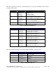
The following tables provide more detailed information conveyed by the LEDs on the front and rear panel of the router: Name State Description System Power Off Blinking Green Solid Green Solid Orange Off Solid Green Solid Orange Off Blinking Green Solid Green Off Solid Green Power off ROMMON mode Operating normally System Error Detected -48V PS and RPS not present -48V PS or RPS present and functional -48V PS or RPS present and failure detected No interrupts or packet transfer occurring System is servic
The physical interfaces are separated into the logical interfaces from FIPS 140-2 as described in the following table: Router Physical Interface 10/100 Ethernet LAN Ports HWIC Ports Console Port Auxiliary Port ENM Slot VeNoM Slot USB Port 10/100 Ethernet LAN Ports HWIC Ports Console Port Auxiliary Port ENM Slot VeNoM Slot USB Port 10/100 Ethernet LAN Ports HWIC Ports Power Switch Console Port Auxiliary Port ENM Slot 10/100 Ethernet LAN Port LEDs AIM LEDs PVDM LEDs Power LED Activity LEDs Auxiliary LED Compa
2.2.1. User Services Users enter the system by accessing the console port with a terminal program or via IPSec protected telnet or SSH session to a LAN port. The IOS prompts the User for username and password. If the password is correct, the User is allowed entry to the IOS executive program. The services available to the User role consist of the following: Status Functions View state of interfaces and protocols, version of IOS currently running.
and algorithms to be used for each IP range or allow plaintext packets to be set from specified IP address. Bypass Mode The routers implement an alternating bypass capability, in which some connections may be cryptographically authenticated and encrypted while others may not.
2.3 Physical Security The router is entirely encased by a metal, opaque case. The rear of the unit contains HWIC/WIC/VIC connectors, LAN connectors, a CF drive, power connector, console connector, auxiliary connector, USB port, and fast Ethernet connectors. The front of the unit contains the system status and activity LEDs. The top, side, and front portion of the chassis can be removed to allow access to the motherboard, memory, AIM slot, and expansion slots.
2. The tamper evidence label should be placed so that the one half of labels A, B, C, D and E covers the enclosure and the other half covers the port adapter slot. 3. The tamper evidence label should be placed so that the one half of label F covers the enclosure and the other half covers the rear panel. 4. The tamper evidence label should be placed so that one half of labels G and H covers the front panel and the other half covers the enclosure. 5.
Figure 7 – 2851 Tamper Evident Label Placement on the Opacity Shield 2.4 Cryptographic Key Management The router securely administers both cryptographic keys and other critical security parameters such as passwords. The tamper evidence seals provide physical protection for all keys. All keys are also protected by the password-protection on the Crypto Officer role login, and can be zeroized by the Crypto Officer. All zeroization consists of overwriting the memory that stored the key.
Triple-DES SHA-1 HMAC-SHA-1 X9.31 PRNG RSA 275 258 39 83 382 The router is in the approved mode of operation only when FIPS 140-2 approved algorithms are used (except DH and RSA key transport which are allowed in the approved mode for key establishment despite being non-approved). Note: The module supports DH key sizes of 1024 and 1536 bits and RSA key sizes of 1024, 1536 and 2048 bits.
The Crypto Officer needs to be authenticated to store keys. All Diffie-Hellman (DH) keys agreed upon for individual tunnels are directly associated with that specific tunnel only via the IKE protocol. RSA Public keys are entered into the modules using digital certificates which contain relevant data such as the name of the public key's owner, which associates the key with the correct entity. All other keys are associated with the user/role that entered them.
Diffie Hellman private exponent Diffie Hellman public key DH The private exponent used in Diffie-Hellman (DH) exchange as part of IKE. Zeroized after DH shared secret has been generated. The public key used in DiffieHellman (DH) exchange as part of IKE. Zeroized after the DH shared secret has been generated. Value derived from the shared secret within IKE exchange. Zeroized when IKE session is terminated. The IKE key derivation key for non ISAKMP security associations.
IKE RSA Encrypted Nonce Public Key IPSec encryption key IPSec authentication key Configuration encryption key RSA RSA public key for IKE encrypted nonces. Generated like any RSA, with the “usage-keys” parameter included. The IPSec encryption key. Zeroized when IPSec session is terminated. NVRAM “# crypto key zeroize rsa" DRAM “# Clear Crypto IPSec SA” HMAC-SHA-1 The IPSec authentication key. The zeroization is the same as above.
is zeroized by overwriting it with a new password. RADIUS secret Shared Secret secret_1_0_0 TACACS+ secret Shared Secret TLS server private key TLS server public key TLS premaster secret RSA TLS Encryption Key TLS Integrity Key AES/TRIPLEDES RSA Shared Secret HMAC-SHA-1 The RADIUS shared secret. This shared secret is zeroized by executing the “no radius-server key” command. The fixed key used in Cisco vendor ID generation.
PRNG Seed d r PRNG Seed Key d r Diffie Hellman private exponent r Diffie Hellman public key r skeyid r skeyid_d r skeyid_a r skeyid_e r IKE session encrypt key r IKE session authentication key r ISAKMP preshared r IKE hash key r IKE RSA Authentication private Key IKE RSA Authentication Public Key IKE RSA Encrypted Nonce Private Key IKE RSA Encrypted Nonce Public Key r r r r IPSec encryption key r IPSec authentication key r r w d r w d r w d r w d r w d r w d r w d r w d r w d r w d r w d
Configuration encryption key r w d Router authentication key 1 PPP authentication key Router authentication key 2 r w d r r w d r d r w r w d r SSH session key r w d r User password r w d r w d r w d r w d r Enable password Enable secret RADIUS secret secret_1_0_0 r w d TACACS+ secret TLS server private key r TLS server public key r TLS pre-master secret r TLS Encryption Key r TLS Integrity Key r r w d r w d r w d r w d r w d r w r w r w d r w d r w d r w d r w d r w d Table 6 – Rol
2.5 Self-Tests In order to prevent any secure data from being released, it is important to test the cryptographic components of a security module to insure all components are functioning correctly. The router includes an array of self-tests that are run during startup and periodically during operations. All self-tests are implemented by the software.
HMAC-SHA-1 Known Answer Test RNG Known Answer Test Firmware integrity test Diffie Hellman Test RSA signature gen/ver known answer test o Conditional Tests Pairwise consistency test for RSA signature keys Continuous RNG test for the hardware RNG 2.5.3 • Self-tests performed by Safenet Safenet Self Tests o POST tests AES Known Answer Test Triple-DES Known Answer Test HMAC-SHA-1 Known Answer Test SHA-1 Known Answer Test © Copyright 2007 Cisco Systems, Inc.
3 Secure Operation of the Cisco 2851 router The Cisco 2851 routers meet all the Level 2 requirements for FIPS 140-2. Follow the setting instructions provided below to place the module in FIPS-approved mode. Operating this router without maintaining the following settings will remove the module from the FIPS approved mode of operation. 3.1 Initial Setup 1. The Crypto Officer must apply tamper evidence labels as described in Section 2.4 of this document. 2.
5. RADIUS and TACACS+ shared secret key sizes must be at least 8 characters long. 3.3 IPSec Requirements and Cryptographic Algorithms 1. The only type of key management protocol that is allowed in FIPS mode is Internet Key Exchange (IKE), although manual creation of security associations is also permitted. 2. Although the IOS implementation of IKE allows a number of algorithms, only the following algorithms are allowed in a FIPS 140-2 configuration: ah-sha-hmac esp-sha-hmac esp-Triple-DES esp-aes 3.
3.6 Remote Access 1. Telnet access to the module is only allowed via a secure IPSec tunnel between the remote system and the module. The Crypto officer must configure the module so that any remote connections via telnet are secured through IPSec, using FIPS-approved algorithms. Note that all users must still authenticate after remote access is granted. 2. SSH access to the module is only allowed if SSH is configured to use a FIPS-approved algorithm.
CISCO EDITOR’S NOTE: You may now include all standard Cisco information included in all documentation produced by Cisco. Be sure that the following line is in the legal statements at the end of the document: By printing or making a copy of this document, the user agrees to use this information for product evaluation purposes only. Sale of this information in whole or in part is not authorized by Cisco Systems. © Copyright 2007 Cisco Systems, Inc.