
Specifications


© Copyright 2007 Cisco Systems, Inc. Page 8 of 26
This document may be freely reproduced and distributed whole and intact including this Copyright Notice.
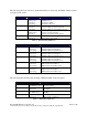
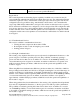
The physical interfaces are separated into the logical interfaces from FIPS 140-2 as described in
the following table:
Router Physical Interface FIPS 140-2 Logical Interface
10/100 Ethernet LAN Ports
HWIC Ports
Console Port
Auxiliary Port
ENM Slot
VeNoM Slot
USB Port
Data Input Interface
10/100 Ethernet LAN Ports
HWIC Ports
Console Port
Auxiliary Port
ENM Slot
VeNoM Slot
USB Port
Data Output Interface
10/100 Ethernet LAN Ports
HWIC Ports
Power Switch
Console Port
Auxiliary Port
ENM Slot
Control Input Interface
10/100 Ethernet LAN Port LEDs
AIM LEDs
PVDM LEDs
Power LED
Activity LEDs
Auxiliary LED
Compact Flash LED
Console Port
Auxiliary Port
USB Port
Status Output Interface
Main Power Plug
Redundant Power Supply Plug
Power Interface
Table 4 – 2851 FIPS 140-2 Logical Interfaces
The CF card that stored the IOS image is considered an internal memory module, because the
IOS image stored in the card may not be modified or upgraded. The card itself must never be
removed from the drive. Tamper evident seal will be placed over the card in the drive.
2.2 Roles and Services
Authentication in Cisco 2851 is role-based. There are two main roles in the router that operators
can assume: the Crypto Officer role and the User role. The administrator of the router assumes
the Crypto Officer role in order to configure and maintain the router using Crypto Officer
services, while the Users exercise only the basic User services. The module supports RADIUS
and TACACS+ for authentication. A complete description of all the management and
configuration capabilities of the router can be found in the Performing Basic System
Management manual and in the online help for the router.