
User guide

Chapter 2
Installation
3
EtherFast® 16-Port and 24-Port 10/100 Ethernet Switches
Installing an Ethernet Switch
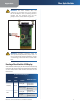
Rack Mounting an Ethernet Switch
Each Ethernet Switch is equipped with three mounting
holes on each side for rack mounting in a standard rack.
After screwing a mounting bracket into each side of an
Ethernet Switch, lift the Switch into your rack and secure
the brackets in place with additional screws (not supplied
by Linksys).
Connecting Nodes to an Ethernet Switch
An Ethernet Switch’s front panel has 16 or 24 standard RJ-
45 ports, depending upon the model, which can connect to
workstations, file servers, print servers, and other network
peripherals. Each port automatically detects port speed
and can operate in either half or full duplex mode. With
duplex detection, you can run speeds of 10Mbps, 20Mbps,
100Mbps, up to a maximum of 200Mbps.
Each cable connected to an Ethernet Switch must be a
UTP Category 5 ethernet network cable with RJ-45 tips,
and must not exceed 100 meters (328 feet) in length.
Ready-to-use network cabling with precrimped ends
are available at most computer retail stores.Automatic
Configuration - DHCP
Connecting PCs
Connect your PCs to an Ethernet Switch’s ports with
straight-through UTP Category 5 cabling. Plug the other
end of the Cat 5 cable into your PC’s network adapter.
Connecting to Other Switches, Hubs, Bridges and
Repeaters
Each port on an Ethernet Switch can also be used to uplink
to another switch, hub, bridge or repeater, serving as an
uplink port. These ports will automatically detect what
kind of cable is connected, either cross-over or straight-
through, and adjust for that cable.
Powering On an Ethernet Switch
Plug in an Ethernet Switch’s AC power cable. The Switch
will first run a diagnostic Self-Test, which just takes a
few seconds. After the test, the Power LED will light up
to indicate that the unit is powered on. As each node is
powered on, the corresponding port’s Link/Activity (Link/
Act) LED will light up.
When data is transmitted or received, the Link/Act LEDs
will flicker.
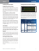
Reading an Ethernet Switch’s LED Display
LED Display
An Ethernet Switch’s LED Display has a Power LED to
indicate when the unit is ON. There are two LEDs per
port: the Link/Activity (Link/Act) LED and the Full Duplex/
Collision (FDX/Col) LED. (An example of the LEDs is shown
above. The LEDs on the switch you purchased may vary
slightly.) See the chart below to find out what the status
of each LED denotes.
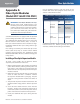
Front Panel LED Displays
LEDs
Network Status
LEDs Color Status
Link/Act Green
Solid light
Connection
Established
Blinking light
Transmitting/
Receiving
FDX/Col Yellow
Solid light
Full duplex
transfer mode
Blinking light Collision
Power Green Solid light
Displays power
status