
Installation guide


1-4
Catalyst 3560 Switch Hardware Installation Guide
OL-6337-03
Chapter 1 Product Overview
Front Panel Description
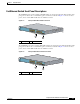
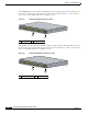
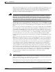
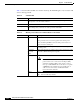
The 10/100 PoE ports on the Catalyst 3560-48PS switch are grouped in pairs. The first member of the
pair (port 1) is above the second member (port 2) on the left, as shown in Figure 1-3. Port 3 is above
port 4, and so on. The SFP module slots are numbered 1 to 4.
Figure 1-3 Catalyst 3560-48PS Switch Front Panel
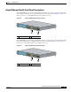
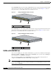
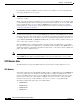
The 10/100 ports on the Catalyst 3560-48TS-S switch are grouped in pairs. The first member of the pair
(port 1) is above the second member (port 2) on the left, as shown in Figure 1-8. Port 3 is above port 4,
and so on. The SFP module slots are numbered 1 to 4.
Figure 1-4 Catalyst 3560G-48TS-S Switch Front Panel
1 10/100 ports 2 SFP module slots
97911
2
1
C
a
ta
l
y
s
t 3
5
6
0
S
E
R
I
E
S
PoE-48
S
Y
S
T
R
P
S
S
T
A
T
D
U
P
L
X
S
P
E
E
D
P
o
E
M
O
D
E
1
2
5
6
7
8
9
1
0
1
1
1
2
1
3
14
1
5
1
6
3
4
1
X
2
X
1
5
X
1
6
X
1
7
18
21
2
2
2
3
2
4
2
5
2
6
2
7
2
8
29
3
0
3
1
3
2
1
9
2
0
1
7
X
1
8
X
3
1
X
3
2
X
33
3
4
3
7
3
8
3
9
4
0
4
1
4
2
4
3
44
4
5
4
6
4
7
4
8
3
5
36
3
3
X
3
4
X
4
7
X
4
8
X
1
2
3
4
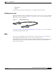
1 10/100 ports 2 SFP module slots
126807
2
1
C
a
t
a
ly
s
t 3
5
6
0
S
E
R
IE
S
S
Y
S
T
R
P
S
S
T
A
T
D
U
P
L
X
S
P
E
E
D
M
O
D
E
1
2
5
6
7
8
9
10
1
1
1
2
1
3
14
1
5
1
6
3
4
1
X
2
X
1
5
X
1
6
X
1
7
1
8
2
1
2
2
2
3
2
4
2
5
2
6
2
7
2
8
2
9
30
3
1
3
2
1
9
2
0
1
7
X
1
8
X
3
1
X
3
2
X
3
3
34
3
7
3
8
3
9
4
0
4
1
4
2
4
3
4
4
45
4
6
4
7
4
8
3
5
3
6
3
3
X
3
4
X
4
7
X
4
8
X
1
2
3
4