
Installation guide


1-10
Catalyst 3560 Switch Hardware Installation Guide
OL-6337-03
Chapter 1 Product Overview
Front Panel Description
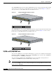
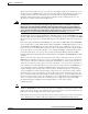
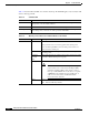
Figure 1-10 Catalyst 3560 Switch LEDs
Note The PoE LED is only visible on Catalyst 3560 switches that support PoE.
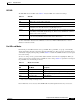
System LED
The System LED shows whether the system is receiving power and is functioning properly. Table 1-1
lists the LED colors and their meanings.
For information on the System LED colors during the power-on self-test (POST), see the “Verifying
Switch Operation” section on page 2-6.
1 Mode button 5 Status LED
2 PoE LED 6 RPS LED
3 Speed LED 7 System LED
4 Duplex LED 8 Port LEDs
1X
2X
11X
12X
1
2
3
4
5
6
7
8
9
10
11
12
SY
S
T
RP
S
ST
A
T
D
U
P
LX
S
PE
E
D
P
o
E
MODE
8
2 3 4 5 6 71
97913
Table 1-1 System LED
Color System Status
Off System is not powered on.
Green System is operating normally.
Amber System is receiving power but is not functioning properly.