
Installation guide


1-14
Catalyst 3560 Switch Hardware Installation Guide
OL-6337-03
Chapter 1 Product Overview
Rear Panel Description
Rear Panel Description
The Catalyst 3560 switch rear panel has an AC power connector, an RPS connector, and an RJ-45
console port. (See Figure 1-11 and Figure 1-12 for examples of the Catalyst 3560 rear panels.)
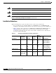
Figure 1-11 Catalyst 3560-24PS and 3560-48PS Switch Rear Panel
Figure 1-12 Catalyst 3560G-24PS, 3560G-48PS, 3560G-24TS, and 3560G-48TS Switch Rear Panel
Power Connectors
The switch is powered through the internal power supply. You can also connect the Cisco RPS 675 to
provide backup power if the switch internal power supply should fail.
Note The Catalyst 3560 switch and the Cisco RPS 675 should be connected to the same AC power source.
1 RJ-45 console port 3 RPS connector
2 AC power connector 4 Fan exhaust
RATING
100-200V ~
5.0A-2.5A, 50-60 HZ
CONSOLE
DC INPUTS FOR REMOTE
POWER SUPPLY
SPECIFIED IN MANUAL
+12v @7.5A -48 @7.8A
97914
1 2 3
4
1 RJ-45 console port 3 RPS connector
2 Fan exhaust 4 AC power connector
CONSOLE
DC INPUTS FOR REMOTE
POWER SUPPLY
SPECIFIED IN MANUAL
119678
1
2
3
4