
Installation guide


2-5
Catalyst 3560 Switch Hardware Installation Guide
OL-6337-03
Chapter 2 Switch Installation
Preparing for Installation
Note When using shorter distances of single-mode fiber cable, you might need to insert an inline optical
attenuator in the link to avoid overloading the receiver.
When the fiber-optic cable span is less than15.43 miles (25 km), you should insert a 5-decibel (dB) or
10-dB inline optical attenuator between the fiber-optic cable plant and the receiving port on the
1000BASE-ZX SFP module at each end of the link.
• Operating environment is within the ranges listed in Appendix A, “Technical Specifications.”
• Clearance to front and rear panels is such that
–
Front-panel indicators can be easily read.
–
Access to ports is sufficient for unrestricted cabling.
–
Rear-panel power connector is within reach of an AC power receptacle.
• Cabling is away from sources of electrical noise, such as radios, power lines, and fluorescent
lighting fixtures. Make sure the cabling is safely away from other devices that might damage the
cables.
• Airflow around the switch and through the vents is unrestricted.
• Temperature around the unit does not exceed 113°F (45°C).
Note If the switch is installed in a closed or multirack assembly, the temperature around it might be
greater than normal room temperature.
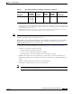
CWDM 1470, 1490,
1510, 1530,
1550, 1570,
1590, 1610
SMF 9/125 — 62 miles (100 km)
1. A mode-conditioning patch cord is required. Using an ordinary patch cord with MMF, 1000BASE-LX/LH SFP modules, and
a short link distance can cause transceiver saturation, resulting in an elevated bit error rate (BER). When using the LX/LH
SFP module with 62.5-micron diameter MMF, you must also install a mode-conditioning patch cord between the SFP module
and the MMF cable on both the sending and receiving ends of the link. The mode-conditioning patch cord is required for link
distances greater than 984 feet (300 m).
2. 1000BASE-ZX SFP modules can send data up to 62 miles (100 km) by using dispersion-shifted SMF or low-attenuation
SMF; the distance depends on the fiber quality, the number of splices, and the connectors.
Table 2-1 Fiber-Optic SFP Module Port Cabling Specifications (continued)
SFP Module
Wavelength
(nanometers) Fiber Type
Core Size
(micron)
Modal
Bandwidth
(MHz/km) Cable Distance