
Installation guide


2-7
Catalyst 3560 Switch Hardware Installation Guide
OL-6337-03
Chapter 2 Switch Installation
Installing the Switch
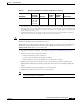
When the switch powers on, it automatically begins the POST, a series of tests that verifies that the
switch functions properly. When the switch begins POST, the system LED slowly blinks green. When
POST completes, the system LED blinks amber. If POST fails, the system LED remains amber. If POST
completes successfully, the system LED rapidly blinks green.
Note POST failures are usually fatal. Call Cisco Systems if your switch does not pass POST.
Powering Off the Switch
After a successful POST, disconnect the power cord from the switch. Install the switch in a rack, on a
wall, on a table, or on a shelf as described in the “Installing the Switch” section on page 2-7.
Installing the Switch
This section describes these installation procedures:
• Rack-Mounting, page 2-7
• Wall-Mounting, page 2-12
• Table- or Shelf- Mounting, page 2-15
Rack-Mounting
To install the switch in a 19-inch or 24-inch rack (24-inch racks require optional mounting hardware),
follow the instructions described in these procedures:
• Removing Screws from the Switch, page 2-8
• Attaching Brackets to the Catalyst 3560 Switch, page 2-9
• Mounting the Switch in a Rack, page 2-11
• Attaching the Cable Guide, page 2-12