
Installation guide


2-19
Catalyst 3560 Switch Hardware Installation Guide
OL-6337-03
Chapter 2 Switch Installation
Connecting to the 10/100 or 10/100/1000 Ports
Connecting to the 10/100 or 10/100/1000 Ports
The switch 10/100 and 10/100/1000 ports configure themselves to operate at the speed of attached
devices. If the attached ports do not support autonegotiation, you can explicitly set the speed and duplex
parameters. Connecting devices that do not autonegotiate or that have their speed and duplex parameters
manually set can reduce performance or result in no linkage.
Note You can configure duplex mode to half, full, or autonegotiate on Gigabit Ethernet interfaces if the speed
is set to 10 or 100 Mbps. You cannot configure half-duplex mode on Gigabit Ethernet interfaces if the
interface speed is 1000 Mbps.
Warning
Voltages that present a shock hazard may exist on Power over Ethernet (PoE) circuits if
interconnections are made using uninsulated exposed metal contacts, conductors, or terminals.
Avoid using such interconnection methods, unless the exposed metal parts are located within a
restricted access location and users and service people who are authorized within the restricted
access location are made aware of the hazard. A restricted access area can be accessed only
through the use of a special tool, lock and key or other means of security.
Statement 1072
To maximize performance, choose one of these methods for configuring the Ethernet ports:
• Let the ports autonegotiate both speed and duplex.
• Set the port speed and duplex parameters on both ends of the connection.
You can configure the 10/100 or 10/100/1000 ports on the Catalyst 3560 PoE switches either to
automatically provide PoE when a Cisco IP Phone, Cisco Aironet Access Point, or end device compliant
with IEEE 802.3af is connected or to never to provide PoE, even if an IP phone or an access point is
connected. The default setting is Auto. To prevent electrostatic-discharge (ESD) damage, follow your
normal board and component handling procedures.
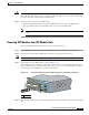
Follow these steps to connect to 10BASE-T or 100BASE-TX devices:
Step 1 When connecting to workstations, servers, routers, and Cisco IP Phones, connect a straight-through
cable to an RJ-45 connector on the front panel. (See Figure 2-18.) When connecting to switches or
repeaters, use a crossover cable. (See the “Cable and Adapter Specifications” section on page B-4 for
cable-pinout descriptions.)
Caution PoE faults are caused when noncompliant cabling or powered devices are connected to a PoE port. Only
standard-compliant cabling can be used to connect Cisco pre-standard IP Phones or wireless access
points or IEEE 802.3af-compliant devices to PoE ports. A cable or device that causes a PoE fault must
be removed from the network.
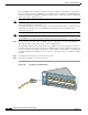
Note You can use the mdix auto interface configuration command in the CLI to enable the automatic
medium-dependent interface crossover (Auto-MDIX) feature. When the Auto-MDIX feature is enabled,
the switch detects the required cable type for copper Ethernet connections and configures the interfaces
accordingly. Therefore, you can use either a crossover or a straight-through cable for connections to a
copper 10/100, 10/100/1000, or 1000BASE-T SFP module port on the switch, regardless of the type of
device on the other end of the connection.