
Installation guide


2-23
Catalyst 3560 Switch Hardware Installation Guide
OL-6337-03
Chapter 2 Switch Installation
Where to Go Next
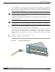
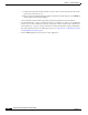
Figure 2-20 Connecting to a 1000BASE-T SFP Module
Step 2
Insert the other cable end in an RJ-45 connector on a target device.
Step 3 Observe the port status LED.
The LED turns green when the switch and the target device have an established link.
The LED turns amber while the STP discovers the network topology and searches for loops. This process
takes about 30 seconds, and then the port LED turns green.
If the LED is off, the target device might not be turned on, there might be a cable problem, or there might
be problem with the adapter installed in the target device. See Chapter 3, “Troubleshooting,” for
solutions to cabling problems.
Step 4 If necessary, reconfigure and restart the switch or target device.
Where to Go Next
If the default configuration is satisfactory, the switch does not need further configuration. You can use
any of these management options to change the default configuration:
• Start CMS, as described in the switch software configuration guide, and configure the switch as a
member of a cluster or as an individual switch. See the Release Notes for the Catalyst 3560 Switch
on Cisco.com for the most current browser requirements.
• Start Network Assistant (which is free) by following these steps:
a. Go to this web address: http://www.cisco.com/go/NetworkAssistant
You must be a registered Cisco.com user, but you need no other access privileges.
b. Find the Network Assistant installer.
1 RJ-45 connector
40
41
42
43
44
45
46
47
48
4
7
X
4
8
X
Catalyst 3560
S
E
R
IE
S
PoE-48
1
2
3
4
97932
1