GETTING STARTED GUIDE Cisco Catalyst 9130AX Series Access Points First Published: October 25, 2019 Last Updated: January 31, 2020 Cisco Systems, Inc. 1 www.cisco.
Cisco Catalyst 9130AX Series Access Points 1 About this Guide 2 About the Cisco Catalyst 9130AX Series Wireless Access Point 3 Safety Instructions 4 Unpacking 5 AP Views, Ports, and Connectors 6 Preparing the AP for Installation 7 Installation Overview 8 Performing a Pre-Installation Configuration 9 Mounting the Access Point 10 Grounding the Access Point 11 Powering the Access Point 12 Configuring and Deploying the Access Point 13 Self-Identifying Antennas 14 Checking the Access Point LED
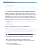
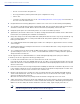
Cisco Catalyst 9130AX Series Access Points 1 About this Guide This guide provides instructions on how to install your Cisco Catalyst 9130AX series access point and provides links to resources that can help you configure it. This guide also provides mounting instructions and troubleshooting information. Note that the C9130AX series access point is referred to as the access point or the AP in this document.
Cisco Catalyst 9130AX Series Access Points — RS-232 Console Interface through RJ-45 — Recovery push button (enables partial or full system configuration recovery) — USB 2.0 Port — One multi-color LED Status indicator. see the “Self-Identifying Antennas” section on page 29 for information on the colors of the LED status indicator. Integrated Bluetooth Low Energy (BLE) radio to enable IoT use cases such as location tracking and wayfinding.
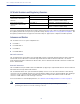
Cisco Catalyst 9130AX Series Access Points AP Model Numbers and Regulatory Domains AP Type Model Number Details Access Point for indoor environments, with internal antennas C9130AXI-x Dual-band, controller-based 802.11ax C9130AXI-EWC-x C9130AXI-x with a Cisco Embedded Wireless Controller software image Access Point for indoor environments, with external antennas C9130AXE-x Dual-band, controller-based 802.
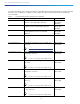
Cisco Catalyst 9130AX Series Access Points The radio and antennas support frequency bands 2400–2500 MHz and 5150–5850 MHz through a common dual-band RF interface. The C-ANT9101=, C-ANT9102=, and C-ANT9103= support frequency bands 2400–2500 MHz and 5150–7125 MHz. Table 1 List of External Antennas Supported on C9130AXE Part Number Description Gain C-ANT9101= Ceiling Mount Omni Self-Identifying Antenna with Bluetooth, 8-port, with DART connectors. 2 dBi (2.
Cisco Catalyst 9130AX Series Access Points Table 1 List of External Antennas Supported on C9130AXE Part Number Description Gain AIR-ANT2566P4W-R= Directional Antenna, 4-port, with RP-TNC connectors. 6 dBi (2.4 GHz) 6 dBi (5 GHz) Note AIR-ANT2566P4W-RS= Connect to AP using AIR-CAB002-D8-R=. Directional Self-Identifying Antenna, 4-port, with RP-TNC connectors. Note 6 dBi (2.4 GHz) 6 dBi (5 GHz) Connect to AP using AIR-CAB002-D8-R=. 1. For the USA, the UNII-1 channels can be used only indoors.
Cisco Catalyst 9130AX Series Access Points Warning Installation of the equipment must comply with local and national electrical codes. Statement 1074 Warning In order to comply with FCC radio frequency (RF) exposure limits, antennas should be located at a minimum of 12 inches (30 cm) or more from the body of all persons. Statement 332 Warning Ultimate disposal of this product should be handled according to all national laws and regulations.
Cisco Catalyst 9130AX Series Access Points 5 AP Views, Ports, and Connectors Figure 1 Face of the 9130AXI Model 1 Status LED 2 Location of the ports and connectors on the head of the AP. 3 9 USB 2.
Cisco Catalyst 9130AX Series Access Points Figure 2 Ports and Connectors on the Head of the C9130AXI Model 1 Kensington lock slot 4 RJ-45 console port 2 Security hasp for padlocking AP to mounting bracket 5 5 GbE port 3 Mode button For information on how to use the Mode button, see “Using the Mode Button” section. 10 USB 2.
Cisco Catalyst 9130AX Series Access Points Figure 3 Face of the C9130AXE Model 1 Location of the Smart Antenna connector port under yellow cap1 3 2 Location of the ports on the head of the AP. 4 Status LED USB 2.0 port 1. Only external antennas with the 8-port DART cable can be connected to this AP.
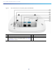
Cisco Catalyst 9130AX Series Access Points The ports and connections on the bottom of the access point are shown in Figure 4. Figure 4 Ports and Connections on the Head of the C9130AXE Model 8-port Smart Antenna (DART) connector port, under a yellow cap1 For more information, see “What is a Smart Antenna connector?” section. 4 Mode button For more information, see “Using the Mode Button” section.
Cisco Catalyst 9130AX Series Access Points d C9130AXI (Internal Antenna) The C9130AXI access point is equipped with four integrated, dual-band antennas omnidirectional in azimuth, for both 2.4 GHz and 5 GHz bands. Figure 3-5 C9130AXI - Dual-band Antenna radiation pattern (2.
Cisco Catalyst 9130AX Series Access Points Figure 3-6 C9130AXI - Dual-band Antenna radiation pattern (2.
Cisco Catalyst 9130AX Series Access Points Figure 3-7 C9130AXI - Dual-band Antenna radiation pattern (5 GHz Azimuth) 15
Cisco Catalyst 9130AX Series Access Points Figure 3-8 C9130AXI - Dual-band Antenna radiation pattern (5 GHz Elevation) 16
Cisco Catalyst 9130AX Series Access Points Figure 3-9 C9130AXI - Single-band Antenna radiation pattern (5 GHz Azimuth) 17
Cisco Catalyst 9130AX Series Access Points Figure 3-10 C9130AXI - Single-band Antenna radiation pattern (5 GHz Elevation) 18
Cisco Catalyst 9130AX Series Access Points Figure 3-11 C9130AXI - AUX Antenna radiation pattern (2.
Cisco Catalyst 9130AX Series Access Points Figure 3-12 C9130AXI - AUX Antenna radiation pattern (2.
Cisco Catalyst 9130AX Series Access Points Figure 3-13 C9130AXI - Bluetooth Antenna radiation pattern (2.
Cisco Catalyst 9130AX Series Access Points Figure 3-14 C9130AXI - Bluetooth Antenna radiation pattern (2.4 GHz Elevation) C9130AXE (External Antenna) The C9130AXE AP models (C9130AXE-x and C9130AXE-EWC-x) are certified for use with external antenna with gains up to 6 dBi or 13 dBi(2.
Cisco Catalyst 9130AX Series Access Points 6 Preparing the AP for Installation Before you mount and deploy your access point, we recommend that you perform a site survey (or use the site planning tool) to determine the best location to install your access point. You should have the following information about your wireless network available: Access point locations. Access point mounting options: below a suspended ceiling, on a flat horizontal surface, or on a desk top.
Cisco Catalyst 9130AX Series Access Points 8 Performing a Pre-Installation Configuration The following procedures ensure that your access point installation and initial operation go as expected. This procedure is optional. Note Performing a pre-installation configuration is an optional procedure. If your network controller is properly configured, you can install your access point in its final location and connect it to the network from there.
Cisco Catalyst 9130AX Series Access Points d. Make sure DHCP is enabled on the network. The access point must receive its IP address through DHCP. Note An 802.11ax Cisco AP will be assigned an IP address from the DHCP server only if a default router (gateway) is configured on the DHCP server (enabling the AP to receive its gateway IP address) and the gateway ARP is resolved. e. CAPWAP UDP ports must not be blocked in the network. f. The access point must be able to find the IP address of the controller.
Cisco Catalyst 9130AX Series Access Points 9 Mounting the Access Point Cisco Catalyst 9130AX series access points can be mounted in several configurations – on a suspended ceiling, on a hard ceiling or wall, on an electrical or network box, and above a suspended ceiling. For access point mounting instructions, go to the following URL: http://www.cisco.com/c/en/us/td/docs/wireless/access_point/mounting/guide/apmount.html The standard mounting hardware supported by the AP is listed in Table 2.
Cisco Catalyst 9130AX Series Access Points Figure 16 1 Locking the AP to the Bracket Position of the hasps for the locks on the back of the AP 10 Grounding the Access Point Warning Only trained and qualified personnel should be allowed to install, replace, or service this equipment. Statement 1030 Grounding is not required for indoor installations.
Cisco Catalyst 9130AX Series Access Points 11 Powering the Access Point Note Always connect the antennas to the C9130AXE before powering the AP up. Enabling the AP radios without connecting the antennas can result in damage to the AP. The AP can be powered only through Power-over-Ethernet (PoE) using the following: 802.3at (PoE+): Any 802.3at (30.0 W) compliant switch port or Cisco Power Injector AIR-PWRINJ6= 802.3af: Any 802.3af (15.
Cisco Catalyst 9130AX Series Access Points DNS discovery—The access point can discover controllers through your domain name server (DNS). For the access point to do so, you must configure your DNS to return controller IP addresses in response to CISCO-CAPWAP-CONTROLLER.localdomain, where localdomain is the access point domain name. Configuring the CISCO-CAPWAP-CONTROLLER provides backwards compatibility in an existing customer deployment.
Cisco Catalyst 9130AX Series Access Points 14 Checking the Access Point LEDs The location of the access point status LED is shown in Figure 1. Note Regarding LED status colors, it is expected that there will be small variations in color intensity and hue from unit to unit. This is within the normal range of the LED manufacturer’s specifications and is not a defect. However, the intensity of the LED can be changed through the controller.
Cisco Catalyst 9130AX Series Access Points If you keep the mode button pressed for more than 60 seconds, the mode button is assumed faulty and no changes are made. Troubleshooting the Access Point to Cisco Controller Join Process Note As specified in the Cisco Wireless Solutions Software Compatibility Matrix, ensure that your controller is running controller software release 8.9.111.0 or IOS-XE 16.12.1 or later to support C9130AXI or 8.10.105.0 or IOS-XE 16.12.2 or later to support C9130AXE.
Cisco Catalyst 9130AX Series Access Points Important Information for Controller-based Deployments Keep these guidelines in mind when you use C9130AX series access point: The access point can only communicate with Cisco wireless controllers. The access point does not support Wireless Domain Services (WDS) and cannot communicate with WDS devices. However, the controller provides functionality equivalent to WDS when the access point joins it. CAPWAP does not support Layer 2.
Cisco Catalyst 9130AX Series Access Points is the IP address of the DNS server, such as 10.0.10.2 Step 3 Add the option 43 line using the following syntax: option 43 hex The hex string is assembled by concatenating the TLV values shown below: Type + Length + Value For example, suppose that there are two controllers with management interface IP addresses, 10.126.126.2 and 10.127.127.2. The type is f1(hex). The length is 2 * 4 = 8 = 08 (hex).
Cisco Catalyst 9130AX Series Access Points What is a Smart Antenna connector? The C9130AXE model has a Smart antenna connector (see Figure 17), which is connected directly to the flexible radio. Without a supported external antenna connected to the Smart Antenna connector, the flexible radio can stay only in 2.4 GHz mode. If an external antenna is connected, the flexible radio can be used in the full Flexible Radio Assignment mode.
Cisco Catalyst 9130AX Series Access Points Figure 19 AIR-CAB003-D8-N= DART Connector What is Cisco Multigigabit Ethernet? Cisco Multigigabit Ethernet (mGig) is a unique Cisco innovation also available in the Cisco Catalyst 9130AX series access point. With the increasing popularity of 802.11ax and new wireless applications, wireless devices now require more network bandwidth. Hence, there is a need for a technology that supports speeds higher than 1 Gbps on all cabling infrastructure.
Cisco Catalyst 9130AX Series Access Points 17 Related Documentation All user documentation for the Cisco Catalyst 9130AX series access point is available at the following URL: http://www.cisco.com/c/en/us/support/wireless/aironet-9130AX-series-access-points/tsd-products-support-serieshome.
Cisco Catalyst 9130AX Series Access Points This device complies with Part 15 rules. Operation is subject to the following two conditions: 1. This device may not cause harmful interference, and 2. This device must accept any interference received, including interference that may cause undesired operation. This equipment has been tested and found to comply with the limits of a Class B digital device, pursuant to Part 15 of the FCC Rules.
Cisco Catalyst 9130AX Series Access Points Guidelines for Operating Cisco Catalyst Access Points in Japan This section provides guidelines for avoiding interference when operating Cisco Catalyst access points in Japan. These guidelines are provided in both Japanese and English.
Cisco Catalyst 9130AX Series Access Points Statement 371—Power Cable and AC Adapter English Translation When installing the product, please use the provided or designated connection cables/power cables/AC adaptors. Using any other cables/adaptors could cause a malfunction or a fire. Electrical Appliance and Material Safety Law prohibits the use of UL-certified cables (that have the “UL” shown on the code) for any other electrical devices than products designated by CISCO.
Cisco Catalyst 9130AX Series Access Points Table 4 List of Internal Antennas Supported on C9130AXI Antenna Type Antenna Gain Antenna Impedance Single-Port Single-Band Omni (VPOL) BLE/IOT 4 dBi 50 ohms Single-Port Dual-Band Omni (VPOL) AUX 2.4 GHz—4.
Cisco Catalyst 9130AX Series Access Points Table 5 List of External Antennas Supported on C9130AXE Part Number Description Gain AIR-ANT2524V4C-R= Ceiling Mount Omni Antenna, 4-port, with RP-TNC connectors. 2 dBi (2.4 GHz) 4 dBi (5 GHz) Note AIR-ANT2524V4C-RS= Ceiling Mount Omni Self-Identifying Antenna, 4-port, with RP-TNC connectors. Note AIR-ANT2544V4M-R= AIR-ANT2566D4M-R= AIR-ANT2566D4M-RS= AIR-ANT2566P4W-R= AIR-ANT2566P4W-RS= 6 dBi (2.
Cisco Catalyst 9130AX Series Access Points European Community, Switzerland, Norway, Iceland, and Liechtenstein Access Point Models: C9130AXI-E C9130AXE-E Note This equipment is intended to be used in all EU and EFTA countries. Outdoor use may be restricted to certain frequencies and/or may require a license for operation. For more details, contact Cisco Corporate Compliance.
Cisco Catalyst 9130AX Series Access Points Separation Distance MPE 0.35 mW/cm 2 Distance Limit 30 cm (12 inches) 1.00 mW/cm2 The World Health Organization has stated that present scientific information does not indicate the need for any special precautions for the use of wireless devices.
Cisco Catalyst 9130AX Series Access Points Separation Distance Frequency MPE Distance 2 2.07 W/m 2.4 GHz 30 cm (12 inches) 2 5.4 W/m 9.76 W/m2 3.52 W/m 5 GHz Limit 2 Health Canada states that present scientific information does not indicate the need for any special precautions for the use of wireless devices.
Cisco Catalyst 9130AX Series Access Points The Mobile Manufacturers Forum at this URL: www.mmfai.org Administrative Rules for Cisco Catalyst Access Points in Taiwan This section provides administrative rules for operating Cisco Catalyst access points in Taiwan. The rules for all access points are provided in both Chinese and English.
Cisco Catalyst 9130AX Series Access Points Article 14 The operation of the low-power radio-frequency devices is subject to the conditions that no harmful interference is caused to aviation safety and authorized radio station; and if interference is caused, the user must stop operating the device immediately and can't re-operate it until the harmful interference is clear. The authorized radio station means a radio-communication service operating in accordance with the Communication Act.
Cisco Catalyst 9130AX Series Access Points Communications, Services, and Additional Information Operation of Cisco Catalyst Access Points in Brazil This section contains special information for operation of Cisco Catalyst access points in Brazil.
Cisco Catalyst 9130AX Series Access Points Cisco Bug Search Tool Cisco Bug Search Tool Cisco Bug Search Tool (BST) is a web-based tool that acts as a gateway to the Cisco bug tracking system that maintains a comprehensive list of defects and vulnerabilities in Cisco products and software. BST provides you with detailed defect information about your products and software. © 2020 Cisco Systems, Inc. All rights reserved.