Reference Guide Cisco Aironet Antennas and Accessories Overview Executive Overview This antenna reference guide is intended to provide information to assist in understanding the ® ® issues and concerns of antennas used with a Cisco Aironet wireless LAN system, or wireless bridge system. It details deployment and design, limitations and capabilities, and basic theories ® of antennas.
Reference Guide Each range has different characteristics. The lower frequencies exhibit better range, but with limited bandwidth and hence lower data rates. The higher frequencies have less range and are subject to greater attenuation from solid objects. Direct Sequence Spread Spectrum The Direct Sequence (DS) Spread Spectrum approach involves encoding redundant information into the RF signal. Every data bit is expanded to a string of chips called a chipping sequence or Barker sequence.
Reference Guide Unlike isotropic antennas, dipole antennas are real antennas (dipole antennas are standard on Cisco Aironet access points, base stations, and workgroup bridges). Dipole antennas have a different radiation pattern compared to isotropic antennas. The dipole radiation pattern is 360 degrees in the horizontal plane and 75 degrees in the vertical plane (assuming the dipole antenna is standing vertically) and resembles a donut in shape.
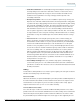
Reference Guide Figure 2. Directional Patch Antenna Figure 3. YAGI Antenna Diversity Antenna Systems Diversity antenna systems are used to overcome a phenomenon known as multipath distortion of multipath fading. It uses two identical antennas, located a small distance apart, to provide coverage to the same physical area. Multipath Distortion Multipath interference occurs when an RF signal has more than one path between a receiver and a transmitter.
Reference Guide Figure 4. Multipath Distortion You can relate this to a common occurrence in your car. As you pull up to a stop, you may notice static on the radio. But as you move forward a few inches or feet, the station starts to come in more clearly. By rolling forward, you move the antenna slightly, out of the point where the multiple signals converge. A diversity antenna system can be compared to a switch that selects one antenna or another, never both at the same time.
Reference Guide The Physical Environment After mobility issues are resolved, the physical environment must be examined. While the area of coverage is the most important determining factor for antenna selection, it is not the sole decision criteria. Building construction, ceiling height, internal obstructions, available mounting locations, and customer aesthetic desires also must be considered. Cement and steel construction have different radio propagation characteristics.
Reference Guide ● Small Office/Small Retail: The standard dipole may provide adequate coverage in these areas depending on the location of the radio device. However, in a back corner office a patch antenna may provide better coverage. It can be mounted to the wall above most obstructions for best performance. Coverage of this type antenna depends on the surrounding environment. ● Enterprise/Large Retail: In most cases, these installations require a large coverage area.
Reference Guide mounting the antenna away from the radio unit. The 100 and 150 foot cables are LMR600 type cable, while the 20 and 50 foot cables are LMR400 type cables. All four lengths are supplied with one RP-TNC plug and one RP-TNC jack connector attached. This allows for connection to the radio unit and to the interconnect cable supplied on the antennas. Connectors According to the US Federal Code of Regulations, products used in the 2.
Reference Guide Figure 5. Cisco Aironet Lightning Arrestor The accepted IEEE transient (surge) suppression is .000008 seconds (8 micro seconds). The Lightning Arrestor is a 50-ohm transmission line with a gas discharge tube positioned between the center conductor and ground. This gas discharge tube changes from an open circuit to a short circuit almost instantaneously in the presence of voltage and energy surges, providing a path to ground for the energy surge.
Reference Guide Increase Factor Decrease Factor 3 dB 2x –3 dB 0.5 x 6 dB 4x –6 dB 0.25 x 10 dB 10 x –10 dB 0.10 x 12 dB 16 x –12 dB 0.06 x 20 dB 100 x –20 dB 0.01 x 30 dB 1000 x –30 dB 0.001 x 40 dB 10,000 x –40 dB 0.0001 x Power Ratings WLAN equipment is usually specified in decibels compared to known values. Transmit Power and Receive Sensitivity are specified in “dBm,” where “m” means 1 milliWatt (mW).
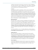
Reference Guide Figure 6. Fresnel Zone Based on both line-of-sight and Fresnel zone requirements, Table 3 provides a guideline on height requirements for 2.4 GHz antennas as various distances. This refers to height above any obstacles located in the middle of the RF path. Table 3. Guideline on Height Requirements for 2.4 GHz Antennas Wireless Link Distance (miles) Approx. Value “F” (60% Fresnel Zone) Ft. at 2.4 GHz Approx. Value “C” (Earth Curvature) Value “H” (mounting Ht.) Ft.
Reference Guide rules are intended to discourage use of amplifiers, high-gain antennas, or other means of significantly increasing RF radiation. The rules are further intended to discourage “home brew” systems which are installed by inexperienced users and which—either accidentally or intentionally—do not comply with FCC regulations for use in the ISM band.
Reference Guide The main issue that comes to question here is, what differentiates a point-to-point from a multipoint system. In Figure 7, point A communicates to a single point, B, and point B communicates to a single point A; therefore, it is simple to see that both locations see this as a point-to-point installation. In Figure 8, point A communicates to more than one (or multiple) points; therefore, point A is operating in a multipoint configuration, and the largest antenna permitted is 16 dBi.
Reference Guide overall gain of the transmitter, plus the antenna gain, less any losses in coax, is equal to or less than +20 dBm. This drastically reduces the overall distance an outdoor link can operate. ● Amplifiers: Since the ETSI regulation has such a low EIRP, the use of amplifiers is typically not permitted in any ETSI system. Frequencies and Channel Sets IEEE 802.11b/g Direct Sequence Channels Fourteen channels are defined in the IEEE 802.11b/g Direct Sequence (DS) channel set.
Reference Guide Channel ID Frequency (MHz) Regulatory Domains (Maximum Conducted Average Power Levels in dBm) 6 2437 X X X X X X X X X X X X X X X X X X X X 7 2442 X X X X X X X X X X X X X X X X X X X X 8 2447 X X X X X X X X X X X X X X X X X X X X 9 2452 X X X X X X X X X X X X X X X X X X X 17 10 2457 X X X X X X X X X X X X X X X X X X X X 11 2462 X X X X X X X X X X X X X X
Reference Guide © 2009 Cisco Systems, Inc. All rights reserved. This document is Cisco Public Information.
Reference Guide Table 5. 802.11a Frequency Plan Regulatory Domain Frequency Band Channel Number ● UNII lower band ● 5.15–5.25 GHz USA ● UNII middle band ● 5.25–5.35 GHz USA ● UNII upper band ● 5.725–5.825 GHz USA ● ISM band ● 5.725–5.825 GHz USA Centre Frequencies ● 36 ● 40 ● 5.180 GHz ● 5.220 GHz ● 44 ● 48 ● 5.230 GHz ● 5.240 GHz ● 52 ● 56 ● 5.260 GHz ● 5.280 GHz ● 60 ● 64 ● 5.300 GHz ● 5.320 GHz ● 149 ● 153 ● 5.745 GHz ● 5.795 GHz ● 157 ● 161 ● 5.785 GHz ● 5.
Reference Guide Cisco Part Number Antenna Type Description Gain AIR-ANT3213 Diversity Omnidirectional Pillar-mount diversity, indoor antenna with two RP-TNC connectors-Cosmetic antenna is ideal for the retail or hospital environment. Includes 36 in. of white RG-58 cable with a separation of coaxial cables that are joined together to form a 10 in. length. Has a tan cloth covering in a 14 in. x 5 in. x 1 in. rectangle. Included are two mounting brackets that will keep the antenna 6 in. off the wall.
Reference Guide Cisco Part Number Antenna Type Description Gain AIR-ANT5135DG-R Omnidirectional Indoor-only gray, non-articulating dipole like omnidirectional antenna for 5 GHz. Use with any radio with 5 GHz connectors. 3.5 dBi AIR-ANT5145V-R Diversity Omnidirectional Indoor-only diversity omnidirectional 5 GHz antenna for use with the 1200 Series and the 802.11a module (AIRRM22A). 4.
Reference Guide Cisco Part Number Antenna Type Description Gain mast or a suitable vertical surface. The antenna is not compatible with other Cisco Aironet radio products operating in the 5 GHz frequency band. AIR-ANT5114P-N Patch 5 GHz, 14 dBi patch antenna for use in the 49505850 MHz frequency band. The antenna has an N-type connector, and will require a separate low loss cable for mounting to the access point. Articulating mount included.
Reference Guide Table 9 below defines the cables available for interconnecting the antennas and the radio devices for the Cisco Aironet product line. Table 12. Cisco Cables Cisco Part Number Type of Cable Description Loss at 2.4 GHz Loss at 5.8 GHz AIR-CAB005LL-N Interconnect 5-ft low loss cable, one straight N connector, one 90-degree N connector 0.5 dB 0.8 dB AIR-CAB005LL-R Interconnect 5-ft low loss cable, one RP-TNC plug, one RP-TNC jack 0.5 dB 0.
Reference Guide Cisco Aironet Antenna Specifications The following section provides detailed descriptions, including physical and electrical specifications for the antennas offered by Cisco for the Cisco Aironet product line. 2.0 dBi Ceiling Mount Omnidirectional AIR-ANT5959 Dimensions and Mounting Specifications Left Antenna Patterns Frequency Range 2.4–2.5 GHz VSWR 1.7:1 Power 5 watts Gain 2.
Reference Guide 2.2 dBi Dipole AIR-ANT4941 Dimensions and Mounting Specifications Azimuth Plane Radiation Pattern Frequency Range 2.4–2.484 GHz VSWR Less than 2:1 Power 5 watts Gain 2.2 dBi Polarization Linear Azimuth 3dB Beamwidth Omnidirectional Elevations 3dB Beamwidth 65 degrees Antenna Connector RP-TNC Cable Length none Dimensions 5.5 in. Mounting To RP-TNC Connector © 2009 Cisco Systems, Inc. All rights reserved. This document is Cisco Public Information.
Reference Guide 2.2 dBi Dipole AIR-ANT2422DW-R Dimensions and Mounting Specifications Azimuth Plane Radiation Pattern Frequency Range 2.4–2.484 GHz VSWR Less than 2:1 Power 5 watts Gain 2.2 dBi Polarization Linear Azimuth 3dB Beamwidth Omnidirectional Elevations 3dB Beamwidth 65 degrees Antenna Connector RP-TNC Cable Length None Dimensions 5.5 in. Mounting To RP-TNC Connector © 2009 Cisco Systems, Inc. All rights reserved. This document is Cisco Public Information.
Reference Guide 2.2 dBi Dipole AIR-ANT2422DG-R Dimensions And Mounting Specifications Azimuth Plane Radiation Pattern Frequency Range 2.4–2.484 GHz VSWR Less than 2:1 Power 5 watts Gain 2.2 dBi Polarization Linear Azimuth 3dB Beamwidth Omnidirectional Elevations 3dB Beamwidth 65 degrees Antenna Connector RP-TNC Cable Length None Dimensions 3.9 in. Mounting To RP-TNC Connector © 2009 Cisco Systems, Inc. All rights reserved. This document is Cisco Public Information.
Reference Guide 5.2 dBi Ceiling Mount Omnidirectional AIR-ANT1728 Dimensions and Mounting Specifications Azimuth Plane Radiation Pattern Frequency Range 2.4–2.83 GHz VSWR Less than 2:1, 1.5:1 Nominal Gain 5.2 dBi Polarization Vertical Azimuth 3dB Beamwidth Omnidirectional 360 degrees Elevations Plan (3dB Beamwidth) 36 degrees Antenna Connector RP-TNC Cable Length 3 ft. (91 m) Dimensions 11.25 in. x 1 in. (28.57 cm x 2.
Reference Guide 5.2 dBi Mast Mount Omnidirectional AIR-ANT2506 Dimensions and Mounting Specifications Azimuth Plane Radiation Pattern Frequency Range 2.4–2.83 GHz VSWR Less than 2:1, 1.5:1 Nominal Gain 5.2 dBi Polarization Vertical Azimuth 3dB Beamwidth Omnidirectional 360 degrees Elevations Plan (3dB Beamwidth) 36 degrees Antenna Connector RP-TNC Cable Length 3 ft (91 m) Dimensions 11..5 in. x 1.125 in. (29.21 cm x 2.
Reference Guide 5.2 dBi Pillar Mount Diversity Omnidirectional AIR-ANT3213 Dimensions and Mounting Specifications Left Antenna Radiation Patterns Frequency Range 2.4–2.83 GHz VSWR 2:1 Nominal Gain 5.2 dBi Polarization Vertical Azimuth 3dB Beamwidth Omnidirectional 360 degrees Elevation 3dB Beamwidth 25 degrees Antenna Connector RP-TNC Cable Length 3 ft. (0.91 cm) Dimensions 14 in. x 5 in. x 1 in. (35.56 cm x 12.7 cm x 2.54 cm) © 2009 Cisco Systems, Inc. All rights reserved.
Reference Guide 6 dBi Wall Mount Directional AIR-ANT2460P-R Dimensions and Mounting Specifications Azimuth Plane Radiation Pattern Frequency Range 2.4–2.5 GHz VSWR Less than 2:1 Gain 6 dBi Polarization Vertical Azimuth 3dB Beamwidth 75 degrees Elevation Plan (3dB Beamwidth) 73 degrees Antenna Connector RP-TNC Cable Length 3 ft. (91 cm) Dimensions 4.1 in. x 3.9 in. x .75 in. (10.41 cm x 9.90 cm x 1.90 cm) Mounting Wall Mount © 2009 Cisco Systems, Inc. All rights reserved.
Reference Guide 6.5 dBi Wall Mount AIR-ANT2465P-R Dimensions and Mounting Specifications Left Antenna Patterns Frequency Range 2.4–2.5 GHz VSWR 1.7:1 Nominal Gain 6.5 dBi Polarization Vertical Azimuth 3dB Beamwidth 75 degrees Elevations Plan (3dB Beamwidth) 57 degrees Antenna Connector RP-TNC Cable Length 3 ft. (91 cm) Dimensions 5 in. x 6.7 in. x .90 in. (12.7 cm x 17.0 cm x 2.2 cm) Mounting Wall Mount © 2009 Cisco Systems, Inc. All rights reserved.
Reference Guide 8.5 dBi Wall Mount AIR-ANT2485P-R Dimensions and Mounting Specifications Azimuth Plane Radiation Pattern Frequency Range 2.4–2.5 GHz VSWR 2:1 Max, 1.5:1 Nominal Gain 8.5 dBi Polarization Vertical Azimuth 3dB Beamwidth 66 degrees Elevations 3dB Beamwidth 56 degrees Antenna Connector RP-TNC Cable Length 3 ft. (91 cm) Dimensions 5.3 in. x 5.3 in. x .90 in. (13.5 cm x 13.5 cm x 2.2 cm) Mounting Wall Mount © 2009 Cisco Systems, Inc. All rights reserved.
Reference Guide 5 dBi Sector AIR-ANT2450S-R Dimensions and Mounting Specifications Azimuth Plane Radiation Pattern Frequency Range 2.4–2.5 GHz VSWR 1.5 or less Gain 5.0 dBi Polarization Linear vertical Azimuth 3dB Beamwidth 135 degrees Elevations 3dB Beamwidth 54 degrees Antenna Connector RP-TNC Cable Length 3 ft. (91 cm) Dimensions 6 x 3 x 2 in (15.2 x 7.6 x 5 cm) Mounting Wall Mount © 2009 Cisco Systems, Inc. All rights reserved. This document is Cisco Public Information.
Reference Guide 10 dBi Wall/Mast Mount YAGI AIR-ANT2410Y-R Dimensions and Mounting Specifications Azimuth Plane Radiation Pattern Frequency Range 2.4–2.483 GHz VSWR Less than 2:1 Gain 10 dBi Polarization Vertical Azimuth 3dB Beamwidth 55 degrees Elevations Plan 3dB Beamwidth 47 degrees Antenna Connector RP-TNC Cable Length 3 ft. (91 cm) Dimensions 3 in. x 7.25 in. (7.62 cm x 18.42 cm) Mounting Wall/Mast Mount © 2009 Cisco Systems, Inc. All rights reserved.
Reference Guide 12 dBi Mast Mount Omnidirectional AIR-ANT24120 Dimensions and Mounting Specifications Azimuth Plane Radiation Pattern Frequency Range 2400–2500 MHz VSWR 1.5:1 Gain 12 dBi Polarization Linear, Vertical Azimuth 3dB Beamwidth Omnidirectional 360 degrees Elevation (3dB Beamwidth) 7 degrees Antenna Connector RP-TNC Cable Length 1 ft. (30.48 cm) Dimensions 42 in. x 1.25 in. (106.68 cm x 3.17 cm) Wind Rating 125 MPH Mounting Mast Mount © 2009 Cisco Systems, Inc.
Reference Guide 13.5 dBi Mast/Wall Mount YAGI AIR-ANT1949 Dimensions and Mounting Specifications Azimuth Plane Radiation Pattern Frequency Range 2.4–2.83 GHz VSWR Less than 2:1, 1.5:1 Nominal Gain 13.5 dBi Front to Back Ratio Greater than 25 dB Polarization Vertical Azimuth 3dB Beamwidth 30 degrees Elevations 3dB Beamwidth 25 degrees Antenna Connector RP-TNC Cable Length 3 ft. (91 cm) Dimensions 18 in. x 3 in. (45.72 cm x 7.
Reference Guide 14 dBi Mast Mount Sector AIR-ANT2414S-R Dimensions and Mounting Specifications Azimuth Plane Radiation Pattern Frequency Range 2.4–2.5 GHz VSWR 1.5:1 Gain 14 dBi Polarization Linear, Vertical Azimuth 3dB Beamwidth 90 degrees Elevations 3dB Beamwidth 8.5 degrees Antenna Connector RP-TNC Cable Length 5 ft. (152.4 cm) Dimensions 36 in. x 6 in. x 4 in. (91.44 cm x 15.24 cm x 10.16 cm) Mounting Mast Mount © 2009 Cisco Systems, Inc. All rights reserved.
Reference Guide 21 dBi Mast Mount Parabolic Dish AIR-ANT3338 Dimensions and Mounting Specifications Azimuth Plane Radiation Pattern Frequency Range 2.4–2.83 GHz VSWR Less than 1.8:1, 15:1 Nominal Power 5 watts Gain 21 dBi Front to Back Ratio Greater than 25 dB Maximum Side Lobe -17 dB Polarization Vertical Azimuth 3dB Beamwidth 12 degrees Elevation 3dB Beamwidth 12 degrees Antenna Connector RP-TNC Cable Length 2 ft. (60.96 cm) Dimensions 24 in. x 15.5 in. (60.96 cm x 39.
Reference Guide 3.5 dBi Dipole AIR-ANT5135D-R Dimensions and Mounting Specifications Azimuth Plane Radiation Pattern Frequency Range 5.15–5.85 GHz VSWR 2:1 or better Gain 3.5 dBi Polarization Linear Azimuth 3dB Beamwidth Omnidirectional Elevation Plane Radiation Pattern Elevations 3dB Beamwith 40 degrees Antenna Connector RP-TNC Cable Length none Dimensions 5.3 in. (13.46 cm) Mounting RP-TNC Connector © 2009 Cisco Systems, Inc. All rights reserved.
Reference Guide 3.5 dBi Dipole AIR-ANT5135DW-R Dimensions and Mounting Specifications Azimuth Plane Radiation Pattern Frequency Range 5.15–5.85 GHz VSWR 2:1 or better Gain 3.5 dBi Polarization Linear Azimuth 3dB Beamwidth Omnidirectional Elevation Plane Radiation Pattern Elevations 3dB Beamwith 40 degrees Antenna Connector RP-TNC Cable Length none Dimensions 5.3 in. (13.46 cm) Mounting RP-TNC Connector © 2009 Cisco Systems, Inc. All rights reserved.
Reference Guide 3.5 dBi Dipole AIR-ANT5135DG-R Dimensions and Mounting Specifications Azimuth Plane Radiation Pattern Frequency Range 5.15–5.85 GHz VSWR 2:1 or better Gain 3.5 dBi Polarization Linear Azimuth 3dB Beamwidth Omnidirectional Elevation Plane Radiation Pattern Elevations 3dB Beamwith 40 degrees Antenna Connector RP-TNC Cable Length none Dimensions 3.6 in. (9.14 cm) Mounting RP-TNC Connector © 2009 Cisco Systems, Inc. All rights reserved.
Reference Guide 4.5 dBi Diversity Omnidirectional AIR-ANT5145V-R Dimensions and Mounting Specifications Azimuth Plane Radiation Pattern Frequency Range 5.15–5.85 GHz VSWR 2:1 or better Gain 4.5 dBi Polarization Linear Azimuth 3dB Beamwidth Diversity Omnidirectional Elevations 3dB Beamwidth 50 degrees Antenna Connector RP-TNC Cable Length 3 ft. (91 cm) Dimensions 6.75 in. x 4.1 in. x 1 in. (17.15 cm x 10.41 x 2.54 cm) Mounting Drop ceiling cross member mount © 2009 Cisco Systems, Inc.
Reference Guide 9 dBi Patch / 5 dBi Omnidirectional Integrated Antenna—Part of AP1200 5-GHz Radio Module (Part Number AIR-RM21A) 5 dBi Omni Mode Azimuth Plane Radiation Pattern 9 dBi Patch Mode Azimuth Plane Radiation Pattern 5 dBi Omni Mode Elevation Plane Radiation Pattern 9 dBi Patch Mode Elevation Plane Radiation Pattern Frequency Range 5.15–5.35 GHz VSWR 1.
Reference Guide 6 dBi Omnidirectional AIR-ANT5160V-R Dimensions and Mounting Specifications Azimuth Plane Radiation Pattern Frequency Range 5.15–5.85 GHz VSWR 2:1 or better Gain 6 dBi Polarization Vertical Azimuth 3dB Beamwidth Omnidirectional 360 degrees Elevation 3dB Beamwidth 17 degrees Antenna Connector RP-TNC Cable Length 3 ft. (91 cm) Dimensions 12 in. x 1 in. (30.48 cm x 2.54 cm) © 2009 Cisco Systems, Inc. All rights reserved. This document is Cisco Public Information.
Reference Guide 7 dBi Diversity Patch Wall Mount AIR-ANT5170P-R Dimensions and Mounting Specifications Left Antenna Radiation Pattern Frequency Range 5.1–5.8 GHz VSWR 2:1 or better Gain 7 dBi Polarization Linear and vertical Azimuth Plane 70 degrees Elevation Plane 50 degrees Connectors RP-TNC Cable Length 3 ft. (91 cm) Dimensions 5.7 in x 4.3 in. x 0.7 in. (14.5 cm x 10.9 cm x 1.8 cm) Mounting Wall mount © 2009 Cisco Systems, Inc. All rights reserved.
Reference Guide 9.5 dBi Patch Wall or Articulating Mast Mount AIR-ANT5195P-R Dimensions and Mounting Specifications Azimuth Plane Radiation Pattern Frequency Range 5.1–5.8 GHz VSWR 2:1 or better Gain 9.5 dBi Polarization Linear and vertical Azimuth Plane 50 degrees Elevation Plane 43 degrees Connectors RP-TNC Cable Length 3 ft. (91 cm) Dimensions 5.1 in. x 5.1 in. x 1.0 in. (12.9 cm x 12.9 cm x 2.5 cm) Mounting Wall mount or articulating mast mount © 2009 Cisco Systems, Inc.
Reference Guide 2 dBi and 3 dBi Dual Band Ceiling Mount Omnidirectional AIR-ANT2451V-R= Azimuth Plane Radiation Pattern Elevation Plane Radiation Pattern Azimuth Plane Radiation Pattern Elevation Plane Radiation Pattern Dimensions and Mounting Specifications Azimuth Plane Radiation Pattern Frequency Range 2.4–2.5 GHz; 5.1-5.8GHz VSWR 2:1 Gain ● 2 dBi in 2 .
Reference Guide 5 dBi Direct Mount Omnidirectional AIR-ANT2450V-N Dimensions and Mounting Specifications Azimuth Plane Radiation Pattern Frequency Range 2.4–2.5 GHz VSWR 1:7:1 Gain 5dBi Polarization Linear, Vertical Azimuth 3dB Beamwidth Omni Elevations 3dB Beamwidth 30 degrees Antenna Connector N-male Cable Length none Dimensions 11 in. x 1 in. (27.93 cm x 2.54 cm) Mounting Direct Mount Wind Rating (Operational) 125 mph Wind Rating (Survival) 165 mph © 2009 Cisco Systems, Inc.
Reference Guide 5.5 dBi Omnidirectional AIR-ANT2455V-N Dimensions and Mounting Specifications Azimuth Plane Radiation Pattern Frequency Range 2.4–2.83 GHz VSWR 2:1 or better Gain 5.5 dBi Polarization Linear Azimuth Plane Omnidirectional Elevation Plane 25 degrees Connectors N Cable Length none Dimensions 12.5 in. x 1 in. (31.75 cm x 2.54 cm) Mounting Direct mount © 2009 Cisco Systems, Inc. All rights reserved. This document is Cisco Public Information.
Reference Guide 7.5 dBi Omnidirectional AIR-ANT5175V-N Dimensions and Mounting Specifications Azimuth Plane Radiation Pattern Frequency Range 4.9–5.8 GHz VSWR 2:1 or better Gain 7.5 dBi for 5GHz bands. 6 dBi for 4.9GHz bands. Polarization Linear Azimuth Plane Omnidirectional Elevation Plane 16 degrees Connectors N Cable Length 1 ft. (0.30 m) Dimensions 11.65 in. x 1 in. (29.5 cm x 2.54 cm) Mounting Direct mount © 2009 Cisco Systems, Inc. All rights reserved.
Reference Guide 8 dBi Omnidirectional AIR-ANT2480V-N Dimensions and Mounting Specifications Azimuth Plane Radiation Pattern Frequency Range 2.4-2.5 GHz VSWR 1:6:1 Gain 8 dBi Polarization Linear, Vertical Azimuth 3dB Beamwidth 10 degrees Elevations Plan (3dB Beamwidth) Omnidirectional Antenna Connector N-male Cable Length none Dimensions 19.5 in. x 7/8 in. (49.52 cm x 2.
Reference Guide 8 dBi Direct Mount Omnidirectional AIR-ANT5180V-N Dimensions and Mounting Specifications Azimuth Plane Radiation Pattern Frequency Range 4.9–5.85 GHz VSWR 1:7:1 Gain 8 dBi Polarization Linear, Vertical Azimuth 3dB Beamwidth Omnidirectional Elevations Plane (3dB Beamwidth) 16 degrees Antenna Connector N-male Cable Length none Dimensions 11 in. x 1 in. (27.93 cm x 2.
Reference Guide 9 dBi MAST Mount Omnidirectional AIR-ANT58G9VOA-N Dimensions and Mounting Specifications Azimuth Plane Radiation Pattern Frequency Range 5.725–5.825 GHz Antenna Connector N-Male VSWR 1.5:1 Nominal Maximum Power 4 watts Gain 9 dBi Polarization Vertical Dimensions 20.25 in x .64 in. Cable Length 4.9 ft. (1.5 m) Mounting 1.5–2.5 in.
Reference Guide 9.5 dBi Mast Mount Sector AIR-ANT58G10SSA-N Dimensions and Mounting Specifications Azimuth Plane Radiation Pattern Frequency Range 5.725–5.825 GHz VSWR 1.5:1 Nominal Gain 9.5 dBi Polarization H or V Azimuth 3dB Beamwidth 60 degrees Elevations Plan (3dB Beamwidth) 60 degrees Antenna Connector N-Male Dimensions 4.9 ft. (1.5 m) Maximum Power 4 watts Temperature (Operating) –20°F Min, +60°C Max Mounting 1.5–2.5 in.
Reference Guide 14 dBi Patch AIR-ANT5114P-N Dimensions and Mounting Specifications Azimuth Plane Radiation Pattern Frequency Range 4.9–5.85 GHz VSWR 2:1 Gain ● 4.9–5.4 GHz: 13 dBi ● 5.4–5.85 GHz: 14 dBi Polarization Linear, Vertical Azimuth 3dB Beamwidth 25 degrees Elevations Plane (3dB Beamwidth) 29 degrees Antenna Connector N-female Cable Length 1 ft. (0.30 m) Dimensions 4 1/8 in. x 4 1/8 in. (1.27 cm x 1.27 cm) Mounting Wall or mast © 2009 Cisco Systems, Inc. All rights reserved.
Reference Guide 17 dBi Sector AIR-ANT5117S-N Dimensions and Mounting Specifications Azimuth Plane Radiation Pattern Frequency Range 4.9–5.85 GHz VSWR 2:1 Gain 17 dBi Polarization Linear, Vertical Azimuth 3dB Beamwidth 90 degrees Elevations Plane (3dB Beamwidth) 8 degrees Antenna Connector N-female Cable Length None Dimensions 24 1/2 in. x 2 1/2 in. (30.48 cm x 2.54 cm) Mounting Mast mount Wind Rating (Operational) 125 mph Wind Rating (Survival) 165 mph © 2009 Cisco Systems, Inc.
Reference Guide 28 dBi Mast Mount Dish—5.8 GHz AIR-ANT58G28SDA-N Dimensions and Mounting Specifications Azimuth Plane Radiation Pattern Frequency Range 5.725–5.825 GHz Wind Speed (survival) 125 MPH VSWR 1.5:1 Nominal Antenna Connector N-Male Dimensions 4.9 ft (1.5 m) Gain 28 dBi Maximum Power 4 watts Polarization V or H Azimuth 3dB Beamwidth 4.75 degrees Mounting 1.5–2.5 in. Mast mount Elevations Plan (3dB BW) 4.75 degrees Wind Speed (operational) 100 MPH Dimensions 29 in.
Reference Guide 3.0 dBi Omnidirectional AIR-ANT2430V-R Dimensions and Mounting Specifications Antenna A Radiation Pattern Antenna B Radiation Pattern Antenna C Radiation Pattern Frequency Range 2.4–2.5 GHz VSWR 1.5:1 Gain 3.0 dBi Polarization Linear Azimuth 3dB Beamwidth Omnidirectional Elevations Plan (3dB Beamwidth) 60 degrees Antenna Connectors RP-TNC Cable Length 3 ft. (91 cm) Dimensions 12.1 in. x 4.2 in. x 1.6 in. (30.73 cm x 10.67 cm x 4.
Reference Guide 4.0 dBi Omnidirectional AIR-ANT5140V-R Dimensions and Mounting Specifications Antenna A Radiation Pattern Antenna B Radiation Pattern Antenna C Radiation Pattern Frequency Range 5.1–5.8 GHz VSWR 1.5:1 Nominal Gain 4.0 dBi Polarization Linear Azimuth 3dB Beamwidth Omnidirectional Elevations Plan 3dB Beamwidth 40 degrees Antenna Connector RP-TNC Cable Length 3 ft. (91 cm) Dimensions 6.9 in. x 3 in. x .9 in. (17.53 cm x 7.62 cm x 2.
Reference Guide Cisco Aironet 1100 Series Integrated Antenna Azimuth Plane Radiation Pattern Elevation Plane Radiation Pattern Frequency Range 2.4–2.5GHz Gain 2 dBi Polarization Linear Azimuth 3dB Beamwidth Omni Elevations 3dB Beamwidth 50 degrees Antenna Connector Integrated Mounting Integrated Antenna Type Omni © 2009 Cisco Systems, Inc. All rights reserved. This document is Cisco Public Information.
Reference Guide Cisco Aironet 1130 Series Integrated Antenna 2.4 GHz, 3 dBi Azimuth Plane Radiation Pattern 5 GHz, 4.5 dBi Azimuth Plane Radiation Pattern 2.4 GHz, 3 dBi Elevation Plane Radiation Pattern Frequency Range ● 2.4–2.5GHz ● 5.15–5.8 GHz Gain ● 2.4 GHz: 3 dBi ● 5 GHz: 4.
Reference Guide Cisco Aironet 1140 Series Integrated Antenna 2.4 GHz, 4 dBi Azimuth Plane Radiation Pattern 5 GHz, 3 dBi Azimuth Plane Radiation Pattern 2.4 GHz, 4 dBi Elevation Plane Radiation Pattern Frequency Range ● 2.4–2.5GHz ● 5.15–5.85 GHz Gain ● 2.4 GHz: 4 dBi ● 5 GHz: 3 dBi 5 GHz, 3 dBi Elevation Plane Radiation Pattern Polarization Linear, Vertical Azimuth 3dB Beamwidth Omnidirectional Elevations 3dB Beamwidth 2.
Reference Guide Cisco Aironet 1000 Series Integrated Antenna 2.4 GHz, 6 dBi Azimuth Plane Radiation Pattern 5 GHz, 5 dBi Azimuth Plane Radiation Pattern 2.4 GHz,6 dBi Elevation Plane Radiation Pattern Frequency Range ● 2.4–2.5GHz ● 5.15–5.8 GHz Gain ● 2.4 GHz: 6 dBi ● 5 GHz: 5 dBi Polarization Linear, Vertical Azimuth 3dB Beamwidth ● 2.4 GHz: 70 degrees ● 5 GHz: 55 degrees Elevations 3dB Beamwidth ● 2.
Reference Guide Cisco Aironet 1300 Series Integrated Antenna Azimuth Plane Radiation Pattern Elevation Plane Radiation Pattern Frequency Range 2.4–2.83 GHz Antenna Type 2 x 2 Patch Array Gain 13 dBi Polarization Linear Vertical VSWR 1.5:1 VSWR Nominal E-Plane 3 dB Beamwidth 36 degrees H-Plane 3 dB Beamwidth 38 degrees © 2009 Cisco Systems, Inc. All rights reserved. This document is Cisco Public Information.
Reference Guide Cisco Aironet 1400 Series Integrated Antenna Azimuth Plane Radiation Pattern Elevation Plane Radiation Pattern Frequency Range 5.725 to 5.825 GHz Antenna Type Patch Array Gain 22.5 dBi Polarization Linear Vertical VSWR 1.5:1 VSWR Nominal E-Plane 3 dB Beamwidth 10 degrees H-Plane 3 dB Beamwidth 12 degrees Printed in USA © 2009 Cisco Systems, Inc. All rights reserved. This document is Cisco Public Information.
Reference Guide © 2009 Cisco Systems, Inc. All rights reserved. This document is Cisco Public Information.