ADMINISTRATION GUIDE Cisco SPA100 Series Phone Adapters SPA112 and SPA122
Cisco and the Cisco Logo are trademarks of Cisco Systems, Inc. and/or its affiliates in the U.S. and other countries. A listing of Cisco's trademarks can be found at www.cisco.com/go/trademarks. Third party trademarks mentioned are the property of their respective owners. The use of the word partner does not imply a partnership relationship between Cisco and any other company. (1005R) © 2011 Cisco Systems, Inc. All rights reserved.
Contents Chapter 1: Getting Started with the Cisco SPA100 Series Phone Adapters 6 Feature Overview 6 Before You Begin 7 Product Features 8 Connecting the Equipment 10 Overview of the Configuration Utility 11 Launching the Configuration Utility 11 Chapter 2: Quick Setup for Voice over IP Service 14 Chapter 3: Configuring the Network 16 Basic Setup 16 Internet Settings 17 Network Service (SPA122 Only) 19 Network Settings for the LAN and DHCP Server (SPA122 Only) 20 Time Settings 24
Contents Optimizing Fax Completion Rates Configuring Dial Plans 40 42 Digit Sequences 43 Acceptance and Transmission of the Dialed Digits 47 Dial Plan Timer (Off-Hook Timer) 48 Interdigit Long Timer (Incomplete Entry Timer) 50 Interdigit Short Timer (Complete Entry Timer) 50 Resetting the Control Timers 51 Configuring Voice Settings 52 Voice System Information 52 Voice System Settings 56 Voice Provisioning Settings 58 SIP Settings 63 Voice System Regional Settings 73 Line 1 and
Contents Firmware Upgrade 128 Configuration Management 128 Backup Configuration 128 Restore Configuration 129 Reboot 129 Chapter 6: Viewing the Status and Statistics 130 System Information 131 Interface Information 132 Internet Status 133 Port Statistics 134 DHCP Server Information (SPA122) 134 Appendix A: Frequently Asked Questions 137 Appendix B: Using the IVR for Administration 140 Appendix C: Installation Options 145 Mounting the ATA 145 Appendix D: Where to Go From Here
1 Getting Started with the Cisco SPA100 Series Phone Adapters Thank you for choosing the Cisco SPA100 Series Phone Adapters. This chapter provides more information about the features of the product and provides instructions about connecting the equipment and getting started in the webbased configuration utility.
1 Getting Started with the Cisco SPA100 Series Phone Adapters Before You Begin The Cisco SPA100 Series ATAs include the models described below.
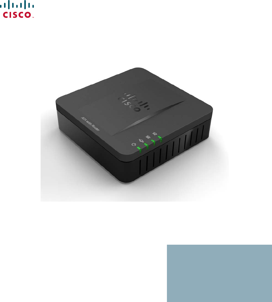
Getting Started with the Cisco SPA100 Series Phone Adapters Product Features 1 Product Features Top Panel The following features are found on the top panel of the ATA. Feature Description Steady green—On hook. Slow flashing green—Off hook. PHONE 1 PHONE 2 Off—Port not ready. Flashing green—Transmitting or receiving data through the INTERNET (WAN) port. INTERNET Off—No link. Steady green—System ready, IP address acquired. SYSTEM Slow flashing green—Acquiring IP address. (By default, uses DHCP.
Getting Started with the Cisco SPA100 Series Phone Adapters Product Features 1 Back Panel The following features are found on the back panel of the ATA. SPA112 SPA122 Feature Description RESET Using a paperclip or similar object, press this button briefly to restart the unit. Press and hold for 20 seconds to restore the factory default settings. All user-changeable non-default settings will be lost. This may include network and service provider data.
1 Getting Started with the Cisco SPA100 Series Phone Adapters Connecting the Equipment Feature Description DC 5V POWER Connect to a power source, by using the provided power adapter. Connecting the Equipment NOTE For wall-mounting instructions, see Mounting the ATA, page 145. STEP 1 Connect one end of the provided Ethernet cable to the INTERNET (Blue) port. Connect the other end directly to your broadband network device. STEP 2 Connect one end of the provided phone cable to the PHONE 1 (Gray) port.
Getting Started with the Cisco SPA100 Series Phone Adapters Overview of the Configuration Utility 1 Overview of the Configuration Utility Launching the Configuration Utility STEP 1 Connect your computer to the same subnet as the ATA. For example, if the ATA is connected to a LAN port on your router, also connect your computer to a LAN port on your router. Note: The SPA122 includes a DHCP server that is enabled by default.
1 Getting Started with the Cisco SPA100 Series Phone Adapters Overview of the Configuration Utility Elements of the User Interface The following features appear in the user interface. 1 3 2 Component Description 1. Menu Bar Provides access to the modules of the configuration utility. Click a menu to view the options in the navigation tree. 2. Navigation Tree Provides access to the configuration pages within the selected module. Click a category heading to view the list of features.
Getting Started with the Cisco SPA100 Series Phone Adapters Overview of the Configuration Utility 1 Configuration Utility Icons Many configuration pages provide the following icons for common tasks. Icon Description Edit Icon The Edit icon lets you edit an existing item from a list. After making your changes, click the Submit button to save your changes. Add Item Icon The Add Item icon lets you add an item to a list. After you have created a new item, click the Submit button to save the new item.
2 Quick Setup for Voice over IP Service The Quick Setup page is displayed by default when you first log on ATA. You can use this page to quickly configure the PHONE ports to ensure connectivity to your provider’s Voice over IP network. NOTE Connecting to your service provider’s network requires Internet connectivity. With the default network settings, your ATA should have Internet connectivity when you connect a cable from the WAN port of the ATA to a port on your router or broadband network device.
Quick Setup for Voice over IP Service 2 STEP 3 To verify your progress, perform the following tasks: a. Click Voice in the menu bar, and then click Info in the navigation tree. Scroll down to the FXS1 or FXS2 Status section of the page. Verify that the Registration State is Registered. If the line is not registered, you may need to refresh the browser several times because it can take a few seconds for the registration to complete.
3 Configuring the Network This chapter describes how to configure the network settings for your ATA. It includes the following sections: • Basic Setup, page 16 • Advanced Settings, page 25 • Application Settings (SPA122 Only), page 28 Basic Setup Use the Network Setup > Basic Setup pages to configure your Internet connection, local network settings (SPA122 only), and your time settings.
3 Configuring the Network Basic Setup Internet Settings Use the Network Setup > Basic Setup > Internet Settings page to set up your Internet connection. To open this page: Click Network in the menu bar, and then click Basic Setup > Internet Settings in the navigation tree. Enter the settings as described below. After making changes, click Submit to save your settings, or click Cancel to abandon any unsaved entries.
3 Configuring the Network Basic Setup Field PPPoE Settings Description • User Name and Password: Enter the user name and password that you use to log into your ISP network through a PPPoE connection. • Service Name: If provided by your ISP, enter the Service Name. • Connect on Demand: You can configure the ATA to disconnect your Internet connection after a specified period of inactivity (Max Idle Time).
3 Configuring the Network Basic Setup Optional Settings Feature Description Host Name The name of the ATA. The default value is the model number. Your ISP may specify a host name to use. Domain Name The domain name, if specified by your ISP. Otherwise, leave the field blank. Static DNS 1, 2, 3 IP addresses for up to three DNS servers that DHCP clients should use directly for name resolution.
3 Configuring the Network Basic Setup Network Settings for the LAN and DHCP Server (SPA122 Only) Use the Network Setup > Basic Setup > Network Settings page to set the IP address and subnet mask for your local network. Also configure the settings for the built-in DHCP server. To open this page: Click Network Setup in the menu bar, and then click Basic Setup > Network Settings in the navigation tree. Enter the settings as described below.
3 Configuring the Network Basic Setup Field Description IP Reservation: Click the Show DHCP Reservation button to view and manage the DHCP client list. Click the Hide DHCP Reservation button to hide the list. When the list is displayed, you can perform the following tasks: Default Gateway Cisco SPA100 Series Phone Adapters Administration Guide • To reserve a static IP address for a current DHCP client: Check the box for the client in the Select Clients from DHCP Tables list. Click Add Clients.
3 Configuring the Network Basic Setup Field Description Option 66 Provides provisioning server address information to hosts that request this option. Server information can be defined in one of three ways: • None: The ATA uses its own TFTP server to source provisioning files, so it returns its own local IP address to the client. • Remote TFTP Server: The ATA was configured by using this method, and received server information through Option 66 on its WAN interface.
3 Configuring the Network Basic Setup Field Description DNS Proxy When enabled, the DNS proxy relays DNS requests to the current public network DNS server for the proxy, and replies as a DNS resolver to the client device on the network. Click Enabled to enable this feature, or click Disabled to disable it.
3 Configuring the Network Basic Setup Time Settings Use the Network Setup > Basic Setup > Time Settings page to set the time for the ATA. You can configure the system time manually or configure it by using the Network Time Protocol (NTP) server. To open this page: Click Network Setup in the menu bar, and then click Basic Setup > Time Settings in the navigation tree. After making changes, click Submit to save your settings, or click Cancel to abandon any unsaved entries.
3 Configuring the Network Advanced Settings Field Description Resync Timer Enter the Resync timer interval value (in seconds). This timer controls how often the ATA resynchronizes with the NTP server. The default setting is 3600 seconds. Auto Recovery After Reboot Choose this option to allow the ATA to automatically reconnect to the time server after a system reboot.
3 Configuring the Network Advanced Settings Field Description Flow Control Flow control is a mechanism that temporarily stops the transmission of data on a port. For example, a situation might arise where a sending station (computer) is transmitting data faster than some other part of the network (including the receiving station) can accept. The overwhelmed network element will halt the transmission of the sender for a specified period of time.
3 Configuring the Network Advanced Settings Field Description MAC Clone Click Enabled to enable MAC address cloning, or click Disabled to disable this feature. By default this feature is Disabled. MAC Address Enter the MAC address that you want to assign to your ATA. The default value is the current MAC address of your ATA. If your computer’s MAC address is the address that you previously registered for your ISP account, click Clone Your PC’s MAC.
3 Configuring the Network Application Settings (SPA122 Only) Field Description L2TP Passthrough Layer 2 Tunneling Protocol is the method used to enable Point-to-Point sessions via the Internet on the Layer 2 level. Click Enabled to enable this feature, or click Disabled to disable it. The default setting is Enabled. The default setting is Enabled. VLAN Use the Network Setup > Advanced Settings > VLAN page to assign a VLAN ID to your network. The VLAN ID can be any numeral from 3 to 4094.
3 Configuring the Network Application Settings (SPA122 Only) Enter the settings as described below. After making changes, click Submit to save your settings, or click Cancel to abandon any unsaved entries. Field Description QoS Click Always On to enable QoS settings at all times, or click On When Phone In Use to enable it only when there is voice traffic. The default setting is On When Phone In Use.
3 Configuring the Network Application Settings (SPA122 Only) Field Description Status The status of the rule: Enabled or Disabled. Application The application that uses this rule to access a network resource. Port Forwarding Details To display the details, click an entry in the List of Port Forwarding. Field Description WAN Interface Name The WAN interface that is used for this traffic. External Port The port that external clients will use to set up this connection.
3 Configuring the Network Application Settings (SPA122 Only) Manually Adding Port Forwarding (SPA122 Only) Use this page to enter the port forwarding settings for an application. To open this page: On the Network Setup > Application > Port Forwarding page, click the Add Entry button or the pencil icon. Enter the settings as described below. After making changes, click Submit to save your settings, or click Cancel to abandon any unsaved entries.
3 Configuring the Network Application Settings (SPA122 Only) Field Description External Port, Internal Port For single port forwarding, specify the ports to use. For simplicity, the internal and external port numbers will often be the same. However, different external port numbers could be used to differentiate traffic of the same application type intended for different internal servers, or to promote privacy through the use of nonstandard ports.
3 Configuring the Network Application Settings (SPA122 Only) DMZ (SPA122 Only) Use the Network Setup > Application > DMZ page if you need to allow a local device to be exposed to the Internet for a special-purpose service. The specified network device must have its DHCP client function disabled and must have a static IP address to it to ensure that it is reachable at the specified IP address. To reserve an IP address for a device, see Network Settings for the LAN and DHCP Server (SPA122 Only), page 20.
4 Configuring Voice This chapter describes how to configure voice settings and voice services for the ATA. It includes the following sections: • Getting Started with Voice Services • Configuring Voice Settings Getting Started with Voice Services This section describes voice port operations and explains how to complete the initial setup tasks to get your voice services working quickly.
4 Configuring Voice Getting Started with Voice Services Understanding Voice Port Operations The ATA allows calls to be made from locally connected analog handsets or fax machines by using SIP-based Internet phone services.
4 Configuring Voice Getting Started with Voice Services Supported Codecs The ATA voice ports support the following codecs: Codec Description G.711 (A-law and mu-law) Very low complexity codecs that support uncompressed 64 kbps digitized voice transmissions at one through ten 5 ms voice frames per packet. These codecs provide the highest narrow-band voice quality and uses the most bandwidth of any of the available codecs. G.
4 Configuring Voice Getting Started with Voice Services An easy way to support proxy redundancy is to configure your DNS server with a list of SIP proxy addresses. The ATA can be instructed to contact a SIP proxy server in a domain named in the SIP message. The ATA consults the DNS server to get a list of hosts in the given domain that provide SIP services.
4 Configuring Voice Getting Started with Voice Services • Adaptive Jitter Buffer The ATA can buffer incoming voice packets to minimize the impact of variable network delays. This process is known as jitter buffering. The size of the jitter buffer adjusts to changing network conditions. The ATA has a Network Jitter Level control setting for each line of service. The jitter level determines how aggressively the ATA tries to shrink the jitter buffer over time to achieve a lower overall delay.
4 Configuring Voice Getting Started with Voice Services • Echo Cancellation Impedance mismatch between the telephone and the IP Telephony gateway phone port can lead to near-end echo. The ATA has a near-end echo canceller that compensates for impedance mismatch. The ATA also implements an echo suppressor with Comfort Noise Generator (CNG) so that any residual echo is not noticeable. These features are enabled by default.
4 Configuring Voice Getting Started with Voice Services • Event Logging You can enable logging and select the relative priority of events to be logged. The information can be sent to a Syslog Server. For more information, see Voice System Settings, page 56. • SIP over TLS The ATA allows the use of SIP over Transport Layer Security (TLS) SIP over TLS is designed to eliminate the possibility of malicious activity by encrypting the SIP messages between the service provider and the end user.
4 Configuring Voice Getting Started with Voice Services STEP 5 In the Audio Configuration section, enter the following settings to support T.38 fax: • Preferred Codec: G.711u (USA) or G.711a (rest of the world) • Use pref. codec only: yes • Silence Supp Enable: no • Echo Canc Enable: no • FAX Passthru Method: ReINVITE STEP 6 Click Submit to save your settings or click Cancel to abandon the unsaved settings. STEP 7 If you are using a Cisco media gateway for PSTN termination, disable T.
4 Configuring Voice Configuring Dial Plans STEP 4 Monitor the network and record the statistics for jitter, loss, and delay. STEP 5 If faxes fail consistently, capture a copy of the configuration as described below. You can then send this file to Technical Support. a. In your web browser, enter the path for the configuration file: http:///admin/config.xml&xuser= &xpassword= b.
4 Configuring Voice Configuring Dial Plans • Dial Plan Timer (Off-Hook Timer) • Interdigit Long Timer (Incomplete Entry Timer) • Interdigit Short Timer (Complete Entry Timer) • Resetting the Control Timers Digit Sequences A dial plan contains a series of digit sequences, separated by the pipe character: | The entire collection of sequences is enclosed within parentheses.
4 Configuring Voice Configuring Dial Plans Digit Sequence Function Use this format to indicate that certain dialed digits are replaced by other characters when the sequence is transmitted. The dialed digits can be zero or more characters. EXAMPLE 1: <8:1650>xxxxxxx When the user presses 8 followed by a seven digit number, the system automatically replaces the dialed 8 with 1650. If the user dials 85550112, the system transmits 16505550112.
4 Configuring Voice Configuring Dial Plans Digit Sequence Examples The following examples show digit sequences that you can enter in a dial plan. In a complete dial plan entry, sequences are separated by a pipe character (|), and the entire set of sequences is enclosed within parentheses. EXAMPLE: ([1-8]xx | 9, xxxxxxx | 9, <:1>[2-9]xxxxxxxxx | 8, <:1212>xxxxxxx | 9, 1 [2-9] xxxxxxxxx | 9, 1 900 xxxxxxx ! | 9, 011xxxxxx.
4 Configuring Voice Configuring Dial Plans • Local dialing with an automatically inserted 3-digit area code ( [1-8]xx | 9, xxxxxxx | 9, <:1>[2-9]xxxxxxxxx | 8, <:1212>xxxxxxx | 9, 1 [2-9] xxxxxxxxx | 9, 1 900 xxxxxxx ! | 9, 011xxxxxx. | 0 | [49]11 ) 8, <:1212>xxxxxxx This is example is useful where a local area code is required by the carrier but the majority of calls go to one area code. After the user presses 8, an external dial tone sounds. The user can enter any seven-digit number.
4 Configuring Voice Configuring Dial Plans • Informational numbers ( [1-8]xx | 9, xxxxxxx | 9, <:1>[2-9]xxxxxxxxx | 8, <:1212>xxxxxxx | 9, 1 [2-9] xxxxxxxxx | 9, 1 900 xxxxxxx ! | 9, 011xxxxxx. | 0 | [49]11 ) 0 | [49]11 This example includes two digit sequences, separated by the pipe character. The first sequence allows a user to dial 0 for an operator. The second sequence allows the user to enter 411 for local information or 911 for emergency services.
4 Configuring Voice Configuring Dial Plans Terminating Event Processing A timeout occurs. The number is rejected if the dialed digits are not matched to a digit sequence in the dial plan within the time specified by the applicable interdigit timer. The user presses the # key. • The Interdigit Long Timer applies when the dialed digits do not match any digit sequence in the dial plan.
4 Configuring Voice Configuring Dial Plans Examples for the Dial Plan Timer NOTE Red text is used to highlight the elements that are explained in the examples. • Allow more time for users to start dialing after taking a phone off hook. (P9 | (9,8<:1408>[2-9]xxxxxx | 9,8,1[2 9]xxxxxxxxx | 9,8,011xx. | 9,8,xx.|[18]xx) P9 After taking a phone off hook, a user has 9 seconds to begin dialing. If no digits are pressed within 9 seconds, the user hears a reorder (fast busy) tone.
4 Configuring Voice Configuring Dial Plans Interdigit Long Timer (Incomplete Entry Timer) You can think of this timer as the “incomplete entry” timer. This timer measures the interval between dialed digits. It applies as long as the dialed digits do not match any digit sequences in the dial plan. Unless the user enters another digit within the specified number of seconds, the entry is evaluated as incomplete, and the call is rejected.
4 Configuring Voice Configuring Dial Plans SYNTAX 2: sequence Ss Use this syntax to apply the new setting to a particular dialing sequence. s: The number of seconds; if no number is entered after S, the default timer of 5 seconds applies. Examples for the Interdigit Short Timer Set the timer for the entire dial plan. S:6,(9,8<:1408>[2-9]xxxxxx | 9,8,1[2-9]xxxxxxxxx | 9,8,011xx. | 9,8,xx.
4 Configuring Voice Configuring Voice Settings Configuring Voice Settings Use the Voice pages to view and configure the voice settings for your ATA.
4 Configuring Voice Configuring Voice Settings Field Description Customization Used for Remote Configuration by service providers who deploy the ATA to their customers. • Open: Not a Remote Configuration unit. This ATA can be configured by using the configuraton utility. • Pending: This Remote Configuraton unit has not yet connected to the server to get its profile. • Customized: This Remote Configuraton unit has received its profile from the server.
4 Configuring Voice Configuring Voice Settings Field Description SIP Bytes Recv Total number of bytes of SIP messages received (including retransmissions) External IP External IP address used for NAT mapping. Line 1/Line 2 Status Field Description Hook State The hook state of the port: On or Off. Registration State Indicates if the line has registered with the SIP proxy. Last Registration At Last date and time the line was registered.
4 Configuring Voice Configuring Voice Settings Field Description Call 1 and 2 State Can take one of the following values: • Idle • Collecting PSTN Pin • Invalid PSTN PIN • PSTN Caller Accepted • Connected to PSTN Call 1 and 2 Tone Type of tone used by the call. Call 1 and 2 Encoder Codec used for encoding. Call 1 and 2 Decoder Codec used for decoding. Call 1 and 2 FAX Status of the fax pass-through mode. Call 1 and 2 Type Direction of the call.
4 Configuring Voice Configuring Voice Settings Field Description Call 1 and 2 Peer Phone Phone number of the peer phone. Call 1 and 2 Call Duration Duration of the call. Call 1 and 2 Packets Sent Number of packets sent Call 1 and 2 Packets Recv Number of packets received. Call 1 and 2 Bytes Sent Number of bytes sent. Call 1 and 2 Bytes Recv Number of bytes received. Call 1 and 2 Decode Latency Number of milliseconds for decoder latency.
4 Configuring Voice Configuring Voice Settings • Partners can download the Syslog Server for SPA Devices by using the link below (login required): www.cisco.com/en/US/partner/prod/collateral/voicesw/ps6788/phones/ ps10499/syslog_server_for_spa_devices.zip Enter the settings as described below. After making changes, click Submit to save your settings, or click Cancel to abandon any unsaved entries. System Configuration Field Description Restricted Access Domains Feature not currently used by the ATA.
4 Configuring Voice Configuring Voice Settings Voice Provisioning Settings Use the Voice > Provisioning page to configure various profiles and parameters. To open this page: Click Voice on the menu bar, and then click Provisioning in the navigation tree. Enter the settings as described below. After making changes, click Submit to save your settings, or click Cancel to abandon any unsaved entries.
4 Configuring Voice Configuring Voice Settings Field Description Resync Error Retry Delay Resync retry interval (in seconds) applied in case of resync failure. The ATA has an error retry timer that activates if the previous attempt to sync with the provisioning server fails. The ATA waits to contact the server again until the timer counts down to zero. This parameter is the value that is initially loaded into the error retry timer.
4 Configuring Voice Configuring Voice Settings Field Description Profile Rule This parameter is a profile script that evaluates to the provisioning resync command. The command is a TCP/ IP operation and an associated URL. The TCP/IP operation can be TFTP, HTTP, or HTTPS. If the command is not specified, TFTP is assumed, and the address of the TFTP server is obtained through DHCP option 66. In the URL, either the IP address or the FQDN of the server can be specified.
4 Configuring Voice Configuring Voice Settings Field Description Report Rule The target URL to which configuration reports are sent. This parameter has the same syntax as the Profile_Rule parameter, and resolves to a TCP/IP command with an associated URL. A configuration report is generated in response to an authenticated SIP NOTIFY message, with Event: report. The report is an XML file containing the name and value of all the device parameters. This parameter may optionally contain an encryption key.
4 Configuring Voice Configuring Voice Settings Log Upgrade Request Msg Syslog message issued at the start of a firmware upgrade attempt. Default setting: $PN $MAC -Requesting upgrade $SCHEME:// $SERVIP:$PORT$PATH. Log Upgrade Success Msg Syslog message issued after a firmware upgrade attempt completes successfully. Default setting: $PN $MAC -- Successful upgrade $SCHEME:// $SERVIP:$PORT$PATH -- $ERR. Log Upgrade Failure Msg Syslog message issued after a failed firmware upgrade attempt.
4 Configuring Voice Configuring Voice Settings SIP Settings Use the Voice > SIP page to configure SIP parameters and values. NOTE For a deeper understanding of these fields, refer to Request for Comments (RFC) 3261. To open this page: Click Voice on the menu bar, and then click SIP in the navigation tree. Enter the settings as described below. After making changes, click Submit to save your settings, or click Cancel to abandon any unsaved entries.
4 Configuring Voice Configuring Voice Settings Field Description DTMF Relay MIME Type MIME Type used in a SIP INFO message to signal a DTMF event. Default setting: application/dtmfrelay. Hook Flash MIME Type MIME Type used in a SIP INFO message to signal a hook flash event. Default setting: application/hookflash Remove Last Reg Lets you remove the last registration before registering a new one if the value is different. Select yes or no from the drop-down list. Default setting: no.
4 Configuring Voice Configuring Voice Settings Field Description Mark all AVT Packets If set to yes, all AVT tone packets (encoded for redundancy) have the marker bit set. If set to no, only the first packet has the marker bit set for each DTMF event. Default setting: Yes SIP TCP Port Min Specifies the lowest TCP port number that can be used for SIP sessions. Default setting: 5060. SIP TCP Port Max Specifies the highest TCP port number that can be used for SIP sessions. Default setting: 5080.
4 Configuring Voice Configuring Voice Settings Field Description INVITE Expires INVITE request Expires header value. If you enter 0, the Expires header is not included in the request. Default setting: 240. Range: 0–(231–1) ReINVITE Expires ReINVITE request Expires header value. If you enter 0, the Expires header is not included in the request. Default setting: 30.
4 Configuring Voice Configuring Voice Settings Field Description Reg Retry Intvl Cap The maximum value to cap the exponential backoff retry delay (which starts at Register Retry Intvl and doubles on every REGISTER retry after a failure) In other words, the retry interval is always at Register Retry Intvl seconds after a failure. If this feature is enabled, Reg Retry Random Delay is added on top of the exponential back-off adjusted delay value.
4 Configuring Voice Configuring Voice Settings RTP Parameters Field Description RTP Port Min Minimum port number for RTP transmission and reception. The RTP Port Min and RTP Port Max parameters should define a range that contains at least 4 even number ports, such as 100 –106. Default setting: 16384. RTP Port Max Maximum port number for RTP transmission and reception. Default setting: 16482. RTP Packet Size Packet size in seconds, which can range from 0.01 to 0.16.
4 Configuring Voice Configuring Voice Settings Field Description RTCP Tx Interval Interval for sending out RTCP sender reports on an active connection. It can range from 0 to 255 seconds. During an active connection, the ATA can be programmed to send out compound RTCP packet on the connection. Each compound RTP packet except the last one contains a SR (Sender Report) and a SDES (Source Description) The last RTCP packet contains an additional BYE packet.
4 Configuring Voice Configuring Voice Settings SDP Payload Types Field Description NSE Dynamic Payload NSE dynamic payload type. The valid range is 96-127. Default setting: 100. AVT Dynamic Payload AVT dynamic payload type. The valid range is 96-127. Default setting: 101. INFOREQ Dynamic Payload INFOREQ dynamic payload type. G726r32 Dynamic Payload G726r32 dynamic payload type. Default setting: 2. G729b Dynamic Payload G.729b dynamic payload type. The valid range is 96127. Default setting: 99.
4 Configuring Voice Configuring Voice Settings Field Description G729b Codec Name G.729b codec name used in SDP. Default setting: G729ab. EncapRTP Codec Name EncapRTP codec name used in SDP. Default setting: EncapRTP. NAT Support Parameters Field Description Handle VIA received If you select yes, the ATA processes the received parameter in the VIA header (this value is inserted by the server in a response to anyone of its requests) If you select no, the parameter is ignored.
4 Configuring Voice Configuring Voice Settings Field Description STUN Test Enable If the STUN Enable feature is enabled and a valid STUN server is available, the ATA can perform a NAT-type discovery operation when it powers on. It contacts the configured STUN server, and the result of the discovery is reported in a Warning header in all subsequent REGISTER requests. If the ATA detects symmetric NAT or a symmetric firewall, NAT mapping is disabled. Default setting: no.
4 Configuring Voice Configuring Voice Settings Voice System Regional Settings Use the Voice > Regional page to localize your system with the appropriate regional settings. To open this page: Click Voice on the menu bar, and then click Region in the navigation tree. Defining Ring and Cadence and Tone Scripts To define ring and tone patterns, the ATA uses the concept of scripts.
4 Configuring Voice Configuring Voice Settings FreqScript A mini-script of up to 127 characters that specifics the frequency and level parameters of a tone.
4 Configuring Voice Configuring Voice Settings Example 1—Dial tone: 350@-19,440@-19;10(*/0/1+2) Number of Frequencies = 2 Frequency 1 = 350 Hz at –19 dBm Frequency 2 = 440 Hz at –19 dBm Number of Cadence Sections = 1 Cadence Section 1: Section Length = 10 s Number of Segments = 1 Segment 1: On=forever, with Frequencies 1 and 2 Total Tone Length = 10s Example 2—Stutter tone: 350@-19,440@-19;2(.1/.
4 Configuring Voice Configuring Voice Settings Field Description Busy Tone Played when a 486 RSC is received for an outbound call. Default setting: 480@-5,620@-5;10(.5/.5/1+2) Reorder Tone Played when an outbound call has failed, or after the far end hangs up during an established call. Reorder Tone is played automatically when Dial Tone or any of its alternatives times out. Default setting: 480@-5,620@5;10(.25/.
4 Configuring Voice Configuring Voice Settings Field Description SIT4 Tone Alternative to the Reorder Tone played when an error occurs as a caller makes an outbound call. The RSC to trigger this tone is configurable on the SIP screen. Default setting: 985@-4,1371@-4,1777@-4;20(.380/0/ 1,.274/0/2,.380/0/3,0/4/0) MWI Dial Tone Played instead of the Dial Tone when there are unheard messages in the caller’s mailbox. Default setting: 350@5,440@-5;2(.1/.
4 Configuring Voice Configuring Voice Settings Field Description Ring5 Cadence Cadence script for distinctive ring 5. Default setting: 1(.5/.5) Ring6 Cadence Cadence script for distinctive ring 6. Default setting: 60(.2/.4,.2/.4,.2/4) Ring7 Cadence Cadence script for distinctive ring 7. Default setting: 60(.4/.2,.4/.2,.4/4) Ring8 Cadence Cadence script for distinctive ring 8. Default setting: 60(0.25/9.
4 Configuring Voice Configuring Voice Settings Distinctive Ring/CWT Pattern Names Field Description Ring1 Name Name in an INVITE’s Alert-Info Header to pick distinctive ring/CWT 1 for the inbound call. Default setting: Bellcore-r1. Ring2 Name Name in an INVITE’s Alert-Info Header to pick distinctive ring/CWT 2 for the inbound call. Default setting: Bellcore-r2. Ring3 Name Name in an INVITE’s Alert-Info Header to pick distinctive ring/CWT 3 for the inbound call. Default setting: Bellcore-r3.
4 Configuring Voice Configuring Voice Settings - Ring Frequency: 25 - Ring Voltage: 80Vc Field Description Ring Waveform Waveform for the ringing signal. Choices are Sinusoid or Trapezoid. Default setting: Sinusoid. Ring Frequency Frequency of the ringing signal. Valid values are 10–100 (Hz) Default setting: 20. Ring Voltage Ringing voltage. Choices are 60–90 (V) Default setting: 85. CWT Frequency Frequency script of the call waiting tone. All distinctive CWTs are based on this tone.
4 Configuring Voice Configuring Voice Settings Field Description Call Back Retry Intvl Call back retry interval in seconds. Range: 0–255 seconds. Default setting: 30. Call Back Delay Delay after receiving the first SIP 18x response before declaring the remote end is ringing. If a busy response is received during this time, the ATA still considers the call as failed and keeps on retrying. Default setting: 0.5. VMWI Refresh Intvl Interval between VMWI refresh to the device. Default setting: 0.
4 Configuring Voice Configuring Voice Settings Field Description CPC Duration Duration in seconds for which the tip-to-ring voltage is removed after the caller hangs up. After that, tip-to-ring voltage is restored and dial tone applies if the attached equipment is still off-hook. CPC is disabled if this value is set to 0. Range: 0 to 1.000 second. Resolution is 0.001 second.
4 Configuring Voice Configuring Voice Settings Field Description Cfwd No Ans Act Code Forwards no-answer calls to the extension specified after the activation code. Default setting: *92. Cfwd No Ans Deact Code Cancels call forwarding of no-answer calls. Default setting: *93. Cfwd Last Act Code Forwards the last inbound or outbound calls to the extension specified after the activation code. Default setting: *63. Cfwd Last Deact Code Cancels call forwarding of the last inbound or outbound calls.
4 Configuring Voice Configuring Voice Settings Field Description Block ANC Act Code Blocks all anonymous calls. Default setting: *77. Block ANC Deact Code Removes blocking of all anonymous calls. Default setting: *87. DND Act Code Enables the do not disturb feature. Default setting: *78. DND Deact Code Disables the do not disturb feature. Default setting: *79. CID Act Code Enables caller ID generation. Default setting: *65. CID Deact Code Disables caller ID generation. Default setting: *85.
4 Configuring Voice Configuring Voice Settings Field Description Attn-Xfer Act Code If the code is specified, the user must enter it before dialing the third party for a call transfer. Enter the code for a call transfer. Modem Line Toggle Code Toggles the line to a modem. Default setting: *99. Modem pass-through mode can be triggered only by pre-dialing this code. FAX Line Toggle Code Toggles the line to a fax machine. Default setting: #99. Media Loopback Code Use for media loopback.
4 Configuring Voice Configuring Voice Settings Field Description Feature Dial Services Codes These codes tell the ATA what to do when the user is listening to the first or second dial tone. One or more *codes can be configured into this parameter, such as *72, or *72|*74|*67|*82, etc. The maximum length is 79 characters.
4 Configuring Voice Configuring Voice Settings Vertical Service Announcement Codes Field Description Service Annc Base Number Base number for service announcements. Default setting: blank. Service Annc Extension Codes Extension codes for service announcements. Default setting: blank. Outbound Call Codec Selection Codes Field Description Prefer G711u Code Dial prefix to make G.711u the preferred codec for the call. Default setting: *017110. Force G711u Code Dial prefix to make G.
4 Configuring Voice Configuring Voice Settings Miscellaneous Field Description FXS Port Impedance Sets the electrical impedance of the PHONE port. Choices are: 600, 900, 600+2.16uF, 900+2.16uF, 270+750||150nF, 220+850||120nF, 220+820||115nF, or 200+600||100nF. Default setting: 600. NOTE For New Zealand impedance (370+620||310nF), use 270+750||150nF. FXS Port Input Gain Input gain in dB, up to three decimal places. The range is 6.000 to -12.000. Default setting: -3.
4 Configuring Voice Configuring Voice Settings Field Description Caller ID Method The choices are described below. Default setting: Bellcore(N.Amer, China) • Bellcore (N.Amer,China): CID, CIDCW, and VMWI. FSK sent after first ring (same as ETSI FSK sent after first ring) (no polarity reversal or DTAS) • DTMF (Finland, Sweden): CID only. DTMF sent after polarity reversal (and no DTAS) and before first ring. • DTMF (Denmark): CID only.
4 Configuring Voice Configuring Voice Settings Field Description Feature Invocation Method Select the method you want to use, Default or Sweden default. Default setting: Default. Line 1 and Line 2 Settings (PHONE1 and PHONE2) Use the Voice > Line 1 and Voice > Line 2 pages to configure the settings for voice services through the PHONE1 and PHONE2 ports. To open this page: Click Voice on the menu bar, and then click Line 1 or Line 2 in the navigation tree.
4 Configuring Voice Configuring Voice Settings Field Description Network Jitter Level Determines how jitter buffer size is adjusted by the ATA. Jitter buffer size is adjusted dynamically. The minimum jitter buffer size is 30 milliseconds or (10 milliseconds + current RTP frame size), whichever is larger, for all jitter level settings. However, the starting jitter buffer size value is larger for higher jitter levels.
4 Configuring Voice Configuring Voice Settings Field Description Auth Resync-Reboot If this feature is enabled, the ATA authenticates the sender when it receives the NOTIFY resync reboot (RFC 2617) message. To use this feature, select yes. Otherwise, select no. Default setting: Yes SIP Proxy-Require The SIP proxy can support a specific extension or behavior when it sees this header from the user agent.
4 Configuring Voice Configuring Voice Settings Field Description SIP Debug Option SIP messages are received at or sent from the proxy listen port. This feature controls which SIP messages to log. The choices are described below. Default setting: None. Cisco SPA100 Series Phone Adapters Administration Guide • none—No logging. • 1-line—Logs the start-line only for all messages. • 1-line excl. OPT—Logs the start-line only for all messages except OPTIONS requests/responses. • 1-line excl.
4 Configuring Voice Configuring Voice Settings Field Description RTP Log Intvl The interval for the RTP log. Default setting: 0. Restrict Source IP If Lines 1 and 2 use the same SIP Port value and the Restrict Source IP feature is enabled, the proxy IP address for Lines 1 and 2 is treated as an acceptable IP address for both lines. To enable the Restrict Source IP feature, select yes. Otherwise, select no.
4 Configuring Voice Configuring Voice Settings Field Description Reply 182 On Call Waiting When enabled, the ATA replies with a SIP182 response to the caller if it is already in a call and the line is off-hook. To use this feature select yes. Default setting: no. Use Anonymous With RPID When set to yes, use "anonymous" in the SIP message. Default setting: Yes Use Local Addr In From Use the local ATA IP address in the SIP FROM message. Default setting: no.
4 Configuring Voice Configuring Voice Settings *1xxxxxxxxxx<:@fwd.pulver.com;nat;uid=jsmith;pwd=xyz The syntax for a dial plan expression is described in the table below. Dial Plan Entry Functionality *xx Allow arbitrary 2 digit star code [3469]11 Allow x11 sequences 0 Operator 00 Int’l Operator [2-9]xxxxxx US local number 1xxx[2-9]xxxxxx US 1 + 10-digit long distance number xxxxxxxxxxxx.
4 Configuring Voice Configuring Voice Settings Proxy and Registration Field Description Proxy SIP proxy server for all outbound requests. Outbound Proxy SIP Outbound Proxy Server where all outbound requests are sent as the first hop. Use Outbound Proxy Enables the use of an Outbound Proxy. If set to no, the Outbound Proxy and Use OB Proxy in Dialog parameters are ignored. Default setting: no. Use OB Proxy In Dialog Whether to force SIP requests to be sent to the outbound proxy within a dialog.
4 Configuring Voice Configuring Voice Settings Field Description Proxy Fallback Intvl After failing over to a lower priority server, the ATA waits for the specified Proxy Fallback Interval, in seconds, before retrying the highest priority proxy (or outbound proxy) servers. This parameter is useful only if the primary and backup proxy server list is provided to the ATA via DNS SRV record lookup on the server name.
4 Configuring Voice Configuring Voice Settings Supplementary Service Subscription The ATA provides native support of a large set of enhanced or supplementary services. All of these services are optional. The parameters listed in the following table are used to enable or disable a specific supplementary service. A supplementary service should be disabled if a) the user has not subscribed for it, or b) the Service Provider intends to support similar service using other means than relying on the ATA.
4 Configuring Voice Configuring Voice Settings Field Description CWCID Serv Enable Call Waiting Caller ID Service Default setting: Yes Call Return Serv Enable Call Return Service Default setting: Yes Call Redial Serv Enable Call Redial Service. Call Back Serv Enable Call Back Service. Three Way Call Serv Enable Three Way Calling Service. Three Way Calling is required for Three Way Conference and Attended Transfer. Default setting: Yes Three Way Conf Serv Enable Three Way Conference Service.
4 Configuring Voice Configuring Voice Settings Field Description Feature Dial Serv Enable Feature Dial Service. See the Feature Dial Services Codes parameter For more information. Default setting: Yes Service Announcement Serv Enable Service Announcement Service. Default setting: no Streaming Audio Server (SAS) Field Description SAS Enable To enable the use of the line as a streaming audio source, select yes. Otherwise, select no. If enabled, the line cannot be used for outgoing calls.
4 Configuring Voice Configuring Voice Settings Field Description SAS Inbound RTP Sink This setting works around devices that do not play inbound RTP if the streaming audio server line declares itself as a send-only device and tells the client not to stream out audio. Enter a Fully Qualified Domain Name (FQDN) or IP address of an RTP sink; this value is used by the streaming audio server line in the SDP of its 200 response to an inbound INVITE message from a client.
4 Configuring Voice Configuring Voice Settings Call Feature Settings Field Description Blind Attn-Xfer Enable Enables the ATA to perform an attended transfer operation by ending the current call leg and performing a blind transfer of the other call leg. If this feature is disabled, the ATA performs an attended transfer operation by referring the other call leg to the current call leg while maintaining both call legs. To use this feature, select yes. Otherwise, select no.
4 Configuring Voice Configuring Voice Settings Field Description Enable IP Dialing Enable or disable IP dialing. If IP dialing is enabled, one can dial [userid@] a.b.c.d[:port], where ‘@’, ‘.’, and ‘:’ are dialed by entering *, userid must be numeric (like a phone number) and a, b, c, d must be between 0 and 255, and port must be larger than 255. If port is not given, 5060 is used. Port and User-Id are optional.
4 Configuring Voice Configuring Voice Settings Field Description Third Preferred Codec Third preferred codec for all calls. (The actual codec used in a call still depends on the outcome of the codec negotiation protocol.) Select one of the following: Unspecified, G711u, G711a, G726-16, G726-24, G726-32, G726-40, G729a, or G723. Default setting: Unspecified Use Pref Codec Only To use only the preferred codec for all calls, select yes. (The call fails if the far end does not support this codec.
4 Configuring Voice Configuring Voice Settings Field Description DTMF Process INFO To use the DTMF process info feature, select yes. Otherwise, select no. Default setting: Yes FAX Passthru Method Select the fax passthrough method: None, NSE, or ReINVITE. Default setting: NSE DTMF Process AVT To use the DTMF process AVT feature, select yes. Otherwise, select no. Default setting: Yes FAX Process NSE To use the fax process NSE feature, select yes. Otherwise, select no.
4 Configuring Voice Configuring Voice Settings Field Description DTMF Tx Strict Hold Off Time This parameter is in effect only when "DTMF Tx Mode" is set to "strict," and when"DTMF Tx Method" is set to out-ofband; i.e. either AVT or SIP-INFO. The value can be set as low as 40 ms. There is no maximum limit.
4 Configuring Voice Configuring Voice Settings Field Description Symmetric RTP Enable symmetric RTP operation. If enabled, the SPA3102 sends RTP packets to the source address and port of the last received valid inbound RTP packet. If disabled (or before the first RTP packet arrives) the SPA3102 sends RTP to the destination as indicated in the inbound SDP. Default setting: no FXS Port Polarity Configuration Field Description Idle Polarity Polarity before a call is connected: Forward or Reverse.
4 Configuring Voice Configuring Voice Settings Field Description Cfwd No Ans Delay Delay in sec before Call Forward No Answer triggers. Same as Cfwd All Dest. Default setting: 20 Selective Call Forward Settings Field Description Cfwd Sel1-8 Caller Eight PSTN Caller Number Patterns to be blocked for VoIP gateway services or forwarded to a certain VoIP number. If the caller is blocked, the ATA will not auto-answers the call.
4 Configuring Voice Configuring Voice Settings Field Description Secure Call Setting If yes, all outbound calls are secure calls by default, without requiring the user to dial a star code first. Default setting: no • If Secure Call Setting is set to Yes, all outbound calls are secure. However, a user can disable security for a call by dialing *19 before dialing the target number.
4 Configuring Voice Configuring Voice Settings Field Description Media Loopback Mode The loopback mode to assume locally when making call to request media loopback. Choices are: Source and Mirror. Default setting: Source NOTE If the SRP answers the call, the mode is determined by the caller. Media Loopback Type The loopback type to use when making call to request media loopback operation. Choices are Media and Packet.
4 Configuring Voice Configuring Voice Settings Field Description VMWI Ring Policy The parameter controls when a ring splash is played when a the VM server sends a SIP NOTIFY message to the ATA indicating the status of the subscriber’s mail box. Three settings are available. Default setting: New VM Available • New VM Available: Ring as long as there new voicemail messages. • New VM Becomes Available: Ring at the point when the first new voicemail message is received.
5 Administration Settings This chapter describes the administrative settings for the ATA. It includes the following sections: • User List (Password Management) • Management • Logging • Diagnostics • Factory Defaults • Firmware Upgrade • Configuration Management • Reboot User List (Password Management) Use the Administration > Management > User List page to manage the two user accounts for the configuration utility.
5 Administration Settings Management To update a password: STEP 1 In the User List table, click the pencil icon for the account that you want to update. STEP 2 On the User Account page, enter the username and password, as described below. • Username: Enter a username. • Old Password (administrator account only): Enter the existing password. The default administrator password is admin. The default guest password is cisco. • New Password: Enter up to 32 characters for your new password.
5 Administration Settings Management Web Access Management Use the Administration > Management > Web Access Management page to configure the settings for access to the administration of the ATA. To open this page: Click Administration in the menu bar, and then click Management > Web Access Management in the navigation tree. After making changes, click Submit to save your settings, or click Cancel to abandon any unsaved entries.
5 Administration Settings Management SPA122: Web Access If needed, you can enable web access to the configuration utility. This feature allows you to manage the configuration from a computer on the WAN at your office and from your home computer via the Internet. To access the configuration utility, launch a web browser and enter the URL in the Address bar. The URL must include the specified protocol, the WAN IP address of the ATA, and port number.
5 Administration Settings Management Field Description Web Utility Access Select the protocol to use for access to the configuration utility from a device on the WAN side of the ATA. Choose HTTP and/or HTTPS. For secure Internet access, select HTTPS. The default value is HTTP. Include the specified protocol when you enter the address in your web browser. For example, with the HTTPS protocol, a WAN IP address of 203.0.113.50, and the default Remote Management Port of 80, you would enter: https://203.0.
5 Administration Settings Management TR-069 Use the Administration > Management > TR-069 page to configure communication with an Auto-Configuration Server (ACS) via TR-069 CPE WAN Management Protocol (CWMP). To open this page: Click Administration in the menu bar, and then click Management > TR-069 in the navigation tree. Enter the settings as described below. After making changes, click Submit to save your settings, or click Cancel to abandon any unsaved entries.
5 Administration Settings Management Field Description Periodic Inform Interval The periodic inform interval. The default value is 86400 seconds. Periodic Inform Enable Click Enabled to enable this feature, or click Disabled to disable it. Request Download If applied, ACS may call the Download RPC after it receives the request from the ATA. SNMP Use the Administration > Management > SNMP page to set up Simple Network Management Protocol (SNMP) for the ATA.
5 Administration Settings Management Field Description Set Community Enter a community string for authentication for SNMP SET commands. The default value is private. Settings for SNMPv3 Field Description Enabled, Disabled Click Enabled to enable this feature, or click Disabled to disable it. The default setting is Disabled. R/W User Enter the user name for SNMPv3 authentication. The default value is v3rwuser.
5 Administration Settings Logging Logging The ATA allows you to record incoming, outgoing, and DHCP lists for various events that occur on your network.The Incoming Log displays a temporary list of the source IP addresses and destination port numbers for the incoming Internet traffic. The Outgoing Log displays a temporary list of the local IP addresses, destination URLs/IP addresses, and service/port numbers for the outgoing Internet traffic.
5 Administration Settings Logging Log Setting If logging is enabled on the Administration > Log > Log Module page, the ATA can periodically send the log file to a server or to an email address. Use the Log Setting page to enter the information for your syslog server and email account. NOTE For information about enabling and configuring logging, see Log Module, page 124. To open this page: Click Administration in the menu bar, and then click Log > Log Setting in the navigation tree.
5 Administration Settings Logging Field Description Sender If you wish to send log entries to an email account, complete all of the fields in this section. Enter a valid email address to identify the sender of the email. Example: user1@company.com Receiver Enter a valid email address where the email will be sent. Example: user2@company.com SMTP Server Enter the IP address or domain name of the mail server that you will use to send this email. Example: smtp.gmail.
5 Administration Settings Logging Log Module Use the Administration > Log > Log Module page to enable and configure logging. NOTE As a best practice, Cisco recommends that you enable logging only when needed, and disable logging when you finish the investigation. Logging consumes resources and can impact system performance. To open this page: Click Administration in the menu bar, and then click Log > Log Module in the navigation tree.
5 Administration Settings Logging Field Description Priority Determines the types of events that will be included in the log. The lowest level of logging is Emergency, which is limited to messages about high impact events. The highest level of logging is Debugging, which includes all message types from Emergency upward. • Emergency: Messages about events, such as an imminent system crash, that make the system unusable. Typically this type of message is broadcast to all users.
5 Administration Settings Diagnostics Field Description Syslog Server Check the box in the heading row to include all services in the log file that is transmitted to the syslog server. Alternatively, check the box for kernel or system to include that service in the log file. Diagnostics The ATA includes two built-in diagnostic tools: • Ping Test • Traceroute Test Ping Test Use the Administration > Diagnostics > Ping Test page to test connectivity between the ATA and a destination.
5 Administration Settings Factory Defaults Traceroute Test Use the Administration > Diagnostics > Traceroute page to view the route between the ATA and a destination. To open this page: Click Administration in the menu bar, and then click Diagnostics > Traceroute Test in the navigation tree. STEP 1 Enter the IP address or domain name of the destination. STEP 2 Click Start to Traceroute to start the test. The results appear on the page and are refreshed every 5 seconds.
5 Administration Settings Firmware Upgrade Firmware Upgrade Use the Administration > Firmware Upgrade page to upgrade the firmware on the ATA. It is not necessary to upgrade unless you are experiencing problems with the ATA or if the new firmware has a feature that you want to use. Before upgrading the firmware, download the firmware upgrade file for the ATA at: www.cisco.
5 Administration Settings Reboot Click the Backup button to save the configuration information of the ATA. When the dialog box appears, choose a location where you want to save the .cfg file. Tip: Rename the file with a name that includes the date and time when you did the backup. Restore Configuration User the Administration > Config Management > Restore Configuration page to restore the ATA configuration settings from a previous backup.
6 Viewing the Status and Statistics This chapter describes how to view the status and statistics for the ATA.
6 Viewing the Status and Statistics System Information System Information Use the Status > System Information page to view information about the ATA and its current settings. To open this page: Click Status on the menu bar, and then click System Information in the navigation tree. Field Description Model The model number and product description. Hardware Version The hardware version number. Boot Version The boot firmware version number. Firmware Version The current firmware version.
6 Viewing the Status and Statistics Interface Information Interface Information Use the Status > Interface Information page to view information for LAN (SPA122 only) and WAN interfaces. To open this page: Click Status on the menu bar, and then click Interface Information in the navigation tree. Interface List Field Description Interface The name of the interface: WAN or LAN (SPA122 only). Connect Type The type of connection configured for the interface. IP Address The IP address of the interface.
6 Viewing the Status and Statistics Internet Status Internet Status Use the Status > Internet Status page to view information about the port activity. To open this page: Click Status on the menu bar, and then click Internet Status in the navigation tree. Field Description Link Status The status of the INTERNET (WAN) interface, showing whether the port is connected or disconnected. IP Address The IP address of the INTERNET (WAN) interface. Netmask The subnet mask for the INTERNET (WAN) interface.
6 Viewing the Status and Statistics Port Statistics Port Statistics Use the Status > Port Statistics page to view information about the port activity on the INTERNET (WAN) port and the ETHERNET (LAN) port (SPA122 only). To open this page: Click Status on the menu bar, and then click Port Statistics in the navigation tree. Field Description Input (pkts) The number of packets received by the port. Output (pkts) The number of packets transmitted by the port.
6 Viewing the Status and Statistics DHCP Server Information (SPA122) DHCP Pool Information Field Description Client Name The host name of the DHCP client. IP Address The IP address leased to the client. MAC Address The MAC address of the DHCP client. Expires Time The remaining time in the current DHCP lease, shown in HH:MM:SS (hours:minutes:seconds) format. The page is periodically updated with the new value as the timer counts down.
6 Viewing the Status and Statistics DHCP Server Information (SPA122) Field Description Option 66 The setting for Option 66, which provides provisioning server address information to hosts requesting this option. The ATA may be set to None (internal), Remote TFTP Server, or Manual TFTP Server. TFTP Server The IP address, hostname, or URL of the TFTP server used for provisioning. Option 67 The configuration/bootstrap filename that is provided to hosts that request this option.
A Frequently Asked Questions Q. I cannot connect to the Internet through the ATA. STEP 1 Make sure that the ATA is powered on. The Power/Sys LED should be solid green and not flashing. If the Power LED is flashing, then power off all of your network devices, including the modem, the ATA, and the connected devices. Wait for 30 seconds. Then power on each device in the following order: • Cable or DSL modem • ATA • Connected Devices STEP 2 Check the cable connections.
A Frequently Asked Questions Q. There is no dial tone, and the Phone 1 or 2 LED is not solid green. STEP 1 Make sure the telephone is connected to the appropriate port, PHONE 1 or 2. STEP 2 Disconnect the RJ-11 telephone cable from the PHONE port, and then reconnect it. STEP 3 Make sure your telephone is set to its tone setting (not pulse). STEP 4 Make sure your network has an active Internet connection. Try to access the Internet, and check to see if the ATA WAN LED is flashing green.
Frequently Asked Questions A Q. When I open a web browser, I am prompted for a username and password. How can I bypass this prompt? Launch the web browser and perform the following steps (these steps are specific to Internet Explorer but are similar for other browsers): STEP 1 Select Tools > Internet Options. STEP 2 Click the Connections tab. STEP 3 Select Never dial a connection. STEP 4 Click OK. Q. The DSL telephone line does not fit into the ATA WAN (Internet) port.
B Using the IVR for Administration An IVR system is available to help you to configure and manage your ATA. Use a telephone keypad to select options and to make your entries. To access the IVR menu: STEP 1 Connect an analog phone to a PHONE port of the ATA. STEP 2 Press the star key four times: **** STEP 3 When challenged for a password, log in as an administrator by using the default administrator's password of 1234# or log in as the PHONE port's user by pressing #.
B Using the IVR for Administration • If the menu is inactive for more than one minute, the IVR times out. You will need to re-enter the IVR menu by pressing the star key four times: ****. Your settings take effect after you hang up the telephone or exit the IVR. The ATA may reboot at this time. • To enter the decimal points in an IP address, press the * (star) key. For example, to enter the IP address 191.168.1.
B Using the IVR for Administration IVR Action Menu Option Choices and Instructions Set Network Mask 121 To enter the value, press numbers on the telephone key pad. Press the * (star) key to enter a decimal point. Note: This option is available only after you choose Static IP as the Internet Connection Type, through option 101. Check Gateway IP Address 130 Set Gateway IP Address 131 To enter the value, press numbers on the telephone key pad. Press the * (star) key to enter a decimal point.
B Using the IVR for Administration IVR Action Menu Option Choices and Instructions Set Line 1 SIP Transport 1911 0: UDP 1: TCP 2: TLS Check Line 2 SIP Transport 1920 Set Line 2 SIP Transport 1921 0: UDP 1: TCP 2: TLS Exit IVR 3948 (Spells EXIT on the phone keypad) Allow or prevent WAN access to the administration web server 7932 Factory Reset of Unit 73738 WARNING: All nondefault settings will be lost. This includes network and service provider data.
B Using the IVR for Administration IVR Action Menu Option Choices and Instructions User Factory Reset of Unit 877778 When prompted, press 1 to confirm, or press * (star) to cancel. After you hear “Option successful,” hang up the phone. The ATA reboots. WARNING: All userchangeable non-default settings will be lost. This may include network and service provider data.
C Installation Options This appendix provides information about installation options. Mounting the ATA You can place the ATA on a desktop or mount it on a wall. ! CAUTION To prevent the ATA from overheating, do not operate it in an area that exceeds an ambient temperature of 104°F (40°C). Desktop Placement Place the ATA on a flat surface near an electrical outlet. WARNING Do not place anything on top of the ATA; excessive weight could damage it.
C Installation Options Mounting the ATA Recommended hardware (not included): Two number-six pan-head tapping screws, 5/8-in. length, with anchors for sheet rock installation. 5/8 in. (15.8 mm) WARNING Insecure mounting might damage the ATA or cause injury. Cisco is not responsible for damages incurred by insecure wall-mounting. To mount the unit to the wall: STEP 1 Determine where you want to mount the unit. Verify that the surface is smooth, flat, dry, and sturdy.
D Where to Go From Here Cisco provides a wide range of resources to help you and your customer obtain the full benefits of the ATA. Support Cisco Small Business Support Community www.cisco.com/go/smallbizsupport Online Technical Support and Documentation (Login Required) www.cisco.com/support Cisco Small Business Support and Resources www.cisco.com/go/smallbizhelp Phone Support Contacts www.cisco.com/go/sbsc Downloads and Documentation Firmware www.cisco.