
Getting Started Guide

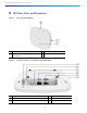

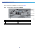
Table Of Contents
- Cisco Catalyst 9130AX Series Access Points
- 1 About this Guide
- 2 About the Cisco Catalyst 9130AX Series Wireless Access Point
- 3 Safety Instructions
- 4 Unpacking
- 5 AP Views, Ports, and Connectors
- 6 Preparing the AP for Installation
- 7 Installation Overview
- 8 Performing a Pre-Installation Configuration
- 9 Mounting the Access Point
- 10 Powering the Access Point
- 11 Configuring and Deploying the Access Point
- 12 Checking the Access Point LEDs
- 13 Miscellaneous Usage and Configuration Guidelines
- 14 FAQs
- 15 Related Documentation
- 16 Declarations of Conformity and Regulatory Information
- Manufacturers Federal Communication Commission Declaration of Conformity Statement
- VCCI Statement for Japan
- Guidelines for Operating Cisco Catalyst Access Points in Japan
- Statement 371—Power Cable and AC Adapter
- Industry Canada
- Canadian Compliance Statement
- European Community, Switzerland, Norway, Iceland, and Liechtenstein
- Declaration of Conformity for RF Exposure
- Generic Discussion on RF Exposure
- This Device Meets International Guidelines for Exposure to Radio Waves
- This Device Meets FCC Guidelines for Exposure to Radio Waves
- This Device Meets the Industry Canada Guidelines for Exposure to Radio Waves
- Cet appareil est conforme aux directives internationales en matière d'exposition aux fréquences radioélectriques
- Additional Information on RF Exposure
- Administrative Rules for Cisco Catalyst Access Points in Taiwan
- Operation of Cisco Catalyst Access Points in Brazil
- Declaration of Conformity Statements
- Communications, Services, and Additional Information
- Cisco Bug Search Tool

3
Cisco Catalyst 9130AX Series Access Points
1 About this Guide
This guide provides instructions on how to install your Cisco Catalyst 9130AX series access point and provides links to
resources that can help you configure it. This guide also provides mounting instructions and troubleshooting information.
Note that the 9130AX series access point is referred to as the access point or the AP in this document.
2 About the Cisco Catalyst 9130AX Series Wireless Access Point
The Cisco Catalyst 9130AX series wireless access point is a dual-band, dual-concurrent, enterprise 802.11ax (Wi-Fi 6)
AP. This AP series has two models, one with integrated antennas and the other with external antennas, which are
designed to use both 2.4 GHz and the 5 GHz bands. This AP series supports a greater overall High Density Experience
(HDX), which provides a more predictable performance for advanced applications such as 4K or 8K videos, high-density
and high-definition collaboration applications, all-wireless offices, and Internet-of-Things (IoT). The AP supports full
interoperability with leading 802.11ax and 802.11ac clients, along with a mixed deployment with other APs and
controllers. These APs provide integrated security, resiliency and operational flexibility as well as increased network
intelligence.
A full listing of the AP's features and specifications are provided in the Cisco Catalyst 9130AX Series Access Point Data
Sheet, at the following URL:
<URL to be added at CCO>
Cisco Catalyst 9130AX Series Wireless Access Point Features
The 9130AX series AP is a wireless controller-based product, and supports:
Four radios, a dual-band 5 GHz (8x8) flexible radio with 2.4 GHz and 4x4 5 GHz, a single-band 5 GHz radio, and an
omni IoT radio that can be used with BLE, Zigbee, Thread and other multi-protocol 802.15.4 devices
Four dual-band and four single-band 5 GHz integrated antennas on the 9130AXI AP models (C9130AXI-x and
C9130AXI-EWC-x).
Note The ‘x’ in the model numbers represents the regulatory domain. For information on supported regulatory
domains, see the“AP Model Numbers and Regulatory Domains” section on page 5.
Integrated internal antennas that are omni directional in azimuth, for both 2.4 GHz and 5 GHz bands.
External antennas on the 9130AXE AP models (C9130AXE-x and C9130AXE-EWC-x).
Multiuser Multiple-Input Multiple-Output (MU-MIMO) technology for uplink and downlink.
Orthogonal Frequency Division Multiple Access (OFDMA)-based scheduling for both uplink and downlink.
Multigigabit Ethernet (mGig)
The following hardware external interfaces:
— 1x100/1000/2500/5000 Multigigabit Ethernet (RJ-45)
— RS-232 Console Interface through RJ-45
— Recovery push button (enables partial or full system configuration recovery)
— USB 2.0 Port