
Specifications


Cisco 7200 VXR Installation and Configuration Guide
OL-5013-08
Chapter 3 Installing a Cisco 7200 VXR Router
Connecting I/O Controller, NPE-G1, or NPE-G2 Cables
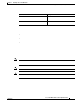
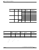
SFP Module
Wavelength
(nm) Fiber Type
Core Size
(microns)
Modal
Bandwidth
(MHz/km) Cable Distance
A mode-conditioning patch cord is required. Using an ordinary patch cord with MMF, 1000BASE-LX/LH SFP modules, and
a short link distance (tens of meters) can cause transceiver saturation resulting in an elevated bit error rate (BER). In addition,
when using the LX/LH SFP module with 62.5-micron diameter MMF, you must install a mode-conditioning patch cord
between the SFP module and the MMF cable on both the transmit and receive ends of the link. The mode-conditioning patch
cord is required for link distances greater than 984 ft (300 m).
62.5
50.0
50.0
500
400
500
1804 ft (550 m)
1804 ft (550 m)
1804 ft (550 m)
SMF 9/10 — 6.2 miles (10
km)
1000BASE-ZX
SFP-GE-Z=
1550 SMF 9/10 — 43.5 miles (70
km)
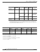
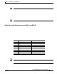
SFP Module Transmit Power Receive Power Power Budget
Minimum Maximum Minimum Maximum
SFP-GE-S= –9.5 dBm
1
1. For fiber types 50/125 µm, NA = 0.20 fiber and 62.5/125 µm, NA = 0.275 fiber.
–4 dBm
1
–17 dBm 0 dBm 7.5 dBm
2
2. For fiber types 50/125 µm MMF and 62.5/125 µm MMF.
SFP-GE-L= –9.5 dBm
3
–11.5dBm
4
3. For fiber types 9/125 µm SMF.
4. For fiber types 62.5/125 µm MMF and 50/125 µm MMF.
–3 dBm
5
5. For fiber types 9/125 µm SMF, 62.5/125 µm MMF, and 50/125 µm MMF.
–20 dBm –3 dBm 7.5 dBm
6
and 8.0
dBm
7
6. For fiber types 50/125 µm MMF and 62.5/125 µm MMF.
7. For fiber type 10 µm SMF.
SFP-GE-Z= 0 dBm 5 dBm –23 dBm 0 dBm –24 dBm