
Specifications

26 Input/Output Controller Replacement Instructions
Removing and Replacing the Input/Output Controller
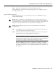
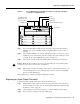
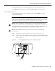
Step 4 Using both hands, grasp the I/O controller by its metal carrier edges and orient the I/O
controller so that its printed circuit board components are upward. (See Figure 7.)
Caution Handle the I/O controller by the carrier edges and handle only; never touch the printed
circuit board components or connector pins.
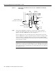
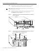
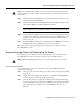
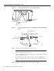
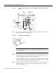
Step 5 Align the left and right edge of the I/O controller’s printed circuit board between the I/O
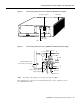
controller slot guides. (For a Cisco 7200 series router, see Figure 16. For a
Cisco uBR7200 series router, see Figure 17.)
Figure 16 Aligning the I/O Controller’s Printed Circuit Board between the Slot Guides in
the Cisco 7200 Series
Figure 17 Aligning the I/O Controller’s Printed Circuit Board between the Slot Guides in
the Cisco uBR7200 Series (Cisco uBR7246 Shown)
H6421
ETHERNET 10BT
ENABLED
0
2
1
3
LINK
0
1
2
3
FAST SERIAL
EN
TD
TC
RD
RC
LB
CD
TD
TC
RD
RC
LB
CD
TD
TC
RD
RC
LB
CD
TD
TC
RD
RC
LB
CD
ENABLED
MII
LINK
RJ45
FAST ETHERNET
0
TOKEN RING
0
1
2
3
0
2
4
6
1
3
5
Metal carrier
Printed circuit board
ETHERNET-10BFL
EN
RX
0
1
2
3
4
TX
RX
TX
RX
TX
RX
TX
RX
TX
Slot guides
MII
EN
RJ45
EN
RJ45
LINK
1O PWR
OK
RJ-45
CPU RESET
FAST ETHERNET INPUT/OUTPUT CONTROLLER
ENABLED
PCMCIA
EJECT
SLOT 0
SLOT 1
FE MII
I/O controller
H11513
Metal carrier Printed circuit board
Slot guide
I/O controller