
Specifications

Input/Output Controller Replacement Instructions 27
Reconnecting Input Power and Powering Up the Router
Caution Do not align the I/O controller’s metal carrier between the slot guides. Doing so will
damage components on the I/O controller’s printed circuit board as you slide the I/O controller into
its chassis slot.
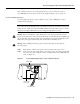
Step 6 Gently slide the I/O controller all the way into its chassis slot until you feel the connectors
make contact with the router midplane.
Step 7 Seat the I/O controller in the router midplane by tightening its captive installation screws
with a number 2 Phillips or a 3/16-inch, flat-blade screwdriver.
Note The I/O controller is not fully seated in the router midplane until you tighten its
captive installation screws (use a number 2 Phillips or a 3/16-inch flat-blade screwdriver).
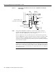
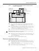
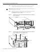
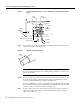
Step 8 Connect the cables to the I/O controller’s console, auxiliary, and Fast Ethernet (if present)
ports. (For a Cisco 7200 series router, see Figure 14. For a Cisco uBR7200 series router,
see Figure 15.) (See the “I/O Controller Connection Equipment and Port Signaling”
section on page 39.)
Step 9 Replace Flash Disks or Flash memory cards (if present) in the PCMCIA slots. (See the
“Installing and Removing a Flash Memory Card” section on page 45.)
This completes the procedure for replacing the I/O controller in a Cisco 7200 series router or
Cisco uBR7200 series router.
Reconnecting Input Power and Powering Up the Router
The following procedures explain how to reconnect input power to a Cisco 7200 series router or
Cisco uBR7200 series router, power up the router, and verify a successful system boot.
Warning Read the installation instructions before you connect the system to its power source.
Reconnecting AC-Input Power
To reconnect AC-input power to a Cisco 7200 series router or Cisco uBR7200 series router,
complete the following steps:
Step 1 At the rear of the router, check that the power switch on the power supply is in the OFF
(O) position.
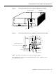
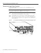
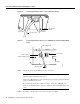
Step 2 Slide the cable-retention clip up (Cisco 7200 series) or to the left (Cisco uBR7200 series),
away from the AC receptacle, and plug in the power cable.
Step 3 Secure the cable in the power supply AC receptacle by sliding the cable-retention clip
down (Cisco 7200 series) or to the right (Cisco uBR7200 series), until it snaps around the
connector. The cable-retention clip provides strain relief for the AC power cable. (For a
Cisco 7200 series router, see Figure 18. For a Cisco uBR7200 series router, see
Figure 19.)