
Specifications
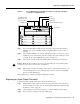

30 Input/Output Controller Replacement Instructions
Removing and Replacing the Input/Output Controller
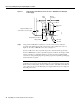
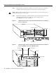
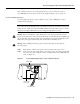
Figure 21 Connecting DC-Input Power to a Cisco uBR7200 Series Universal Broadband
Router
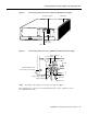
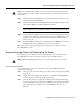
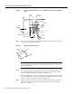
Step 3 If necessary, use a wire stripper to strip approximately 0.55 inch (14 mm) from the –48V,
+48V, and ground leads. (See Figure 22.)
Figure 22 Stripping the DC-Input Leads
Note The ground lead for a Cisco uBR7200 series DC-input power supply consists of a
two-hole grounding lug that connects to an M5 grounding receptacle; you do not need to
strip this ground lead.
Step 4 For a Cisco 7200 series router, insert the stripped end of the ground lead all the way into
the ground lead receptacle on the DC-input power supply, and tighten the receptacle
screw using a 3/16-inch flat-blade screwdriver. (See Figure 20.)
For a Cisco uBR7200 series router, connect the two-hole grounding lug on the grounding
lead to the M5 grounding receptacles with the M5 nuts. Tighten the nuts using the 8-mm
wrench or nut driver (or adjustable wrench). (See Figure 21.)
Step 5 Insert the stripped end of the +48V lead all the way into the +48V lead receptacle and
tighten the receptacle screw using the same 3/16-inch flat-blade screwdriver. Repeat
Step 5 for the –48V lead.
12108
Power
switch
Power
receptacle
Captive
installation
screw
Handle
M5 grounding lug
+48V lead
-48V lead
M5 grounding receptacles
0.55 in.
(14 mm)
H8624