C H A P T E R 1 Product Overview This chapter provides these topics that describe the Catalyst 2900 series XL switches, hereafter referred to as the switches. • Switch features, including management options • Descriptions of the front and rear panels • Descriptions of the LEDs Features The switches are stackable 10/100 Ethernet switches to which you can connect workstations, Cisco IP Phones, and other network devices such as servers, routers, and other switches.
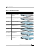
Chapter 1 Product Overview Features • On the Catalyst 2924M XL, Catalyst 2912MF XL, and Catalyst 2924M XL DC switches, two module slots for 10BASE-T/100BASE-TX, 1000BASE-X, 1000BASE-T, Gigabit Ethernet, and asynchronous transfer mode (ATM) modules • On the Catalyst 2924M XL DC switch, a direct current (DC) power converter • On the Catalyst 2912 LRE XL and 2924 LRE XL switches, up to 24 LRE ports through one RJ-21 connector and hot swapping capability with the Cisco LRE customer premises equipment (C
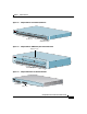
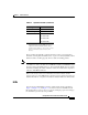
Chapter 1 Product Overview Features Figure 1-1 Catalyst 2900 Series XL Switches Version Number Description WS-C2912-LRE-XL 4 fixed autosensing 10/100 ports 12 LRE ports WS-C2924-LRE-XL WS-C2912-XL INPUT PWR OUTPUT PWR RESET 9X TEMP 10X 11X FAN 12X Cisco RPS 300 4 fixed autosensing 10/100 ports 24 LRE ports INPUT PWR OUTPUT PWR RESET 9X TEMP 10X 11X FAN 12X Cisco RPS 300 12 fixed autosensing 10/100 ports 1X 2X 3X 4X MODE 5X 6X 7X 8X 10BaseT/ 9X 100BASE 10X -TX 11X 12X
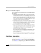
Chapter 1 Product Overview Front-Panel Description Management Interface Options You can configure and monitor individual switches and switch clusters by using these interfaces: • Cluster Management Suite (CMS)—CMS is a graphical user interface that can be launched from anywhere in your network through a web browser such as Netscape Communicator or Microsoft Internet Explorer. CMS is already installed on the switch.
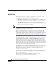
Chapter 1 Product Overview Front-Panel Description 1X 2X Catalyst 2900 XL Front-Panel 10/100 Ports 3X MODE 4X 5X 6X 7X 8X 52646 Figure 1-2 10BASE-T 9X 10X 100BaseF /100BASE -TX X 11X 12X 13X 14X 15X 16X 17X Catalyst 18X 19X 20X 21X 2900 100BAS SERIES E-FX 22X XL 23 24 10/100 ports 100BASE-FX ports Figure 1-3 Catalyst 2900 XL 100BASE-FX ports and Module Slots Expansion slots 2 Catalyst 1 2 MODE 2900 SERIES XL 47286 1 3 4 100BASE -FX 5 6 7 8 9 10 11 12 100BA
Chapter 1 Product Overview Front-Panel Description 10/100 Ports The 10/100 switch ports (see Figure 1-2 and Figure 1-4) can connect to any compatible network device up to 328 feet (100 meters) away: Note • 10BASE-T-compatible devices, such as workstations, Cisco IP Phones, and hubs through standard RJ-45 connectors and Category 3, 4, or 5 cabling • 100BASE-TX-compatible devices, such as high-speed workstations, Cisco IP Phones, servers, hubs, routers, and other switches through standard RJ-45 connec
Chapter 1 Product Overview Front-Panel Description 100BASE-FX Ports The 100BASE-FX ports use 50/125- or 62.5/125-micron multimode fiber-optic cabling. The connection distances between the switch and the attached device can be as follows: • If the switch port and the port on the attached device are configured for half-duplex operation, the connection can be up to 1352 feet (412 meters).
Chapter 1 Product Overview Front-Panel Description (PSTN). For more information about the Cisco LRE 48 POTS Splitter (PS-1M-LRE-48), refer to the Installation Notes for the Cisco LRE 48 POTS Splitter. Note Cisco Long-Reach Ethernet (LRE) products are designed to share lines with analog, Integrated Services Digital Network (ISDN), and digital private branch exchange (PBX) switch telephones that use the 0 to 700 kHz frequency range.
Chapter 1 Product Overview Front-Panel Description Table 1-1 Expansion Modules (continued) Module Type Model Number 1000BASE-T WS-X2932-XL 1Ethernet WS-X2931-XL ATM Gigabit WS-X2971-XL WS-X2972-XL WS-X2951-XL WS-X2961-XL 1. The Ethernet Gigabit module supports several Gigabit Interface Converter (GBIC) devices. For a complete list and the minimum software release required, refer to the Release Notes for the Catalyst 2900 Series XL and Catalyst 3500 Series XL Switches.
Chapter 1 Product Overview Front-Panel Description All of the LEDs described in this section except the utilization meter (UTL) are visible on the Cluster Management Suite (CMS) window and, if the switch is a cluster member, on the CMS Cluster Manager window. The Catalyst 2900 Series XL and Catalyst 3500 Series XL Software Configuration Guide describes how to use CMS to manage standalone or individual switches and how to use cluster management software to manage switch clusters].
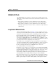
Chapter 1 Product Overview Front-Panel Description Figure 1-6 Catalyst 2912MF XL, 2924M XL, and 2924M XL DC LEDs 10BASE-FX port LEDs 1 2 1 2 MODE 3 4 100BAS E-FX 5 6 48003 7 System LED RPS LED Expansion slot status LED Port mode LED Mode button Catalyst 2900 Series XL Hardware Installation Guide 78-6461-04 1-11
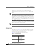
Chapter 1 Product Overview Front-Panel Description Figure 1-7 Catalyst 2912 LRE XL and 2924 LRE XL LEDs 10/100 port LEDs SYSTEM RPS 1X LRE STAT DUPLX SPEED Mode button 2X 3X 4X System LED RPS LED LRE LED STAT LED DUPLEX LED Speed LED 48002 MODE LRE port LEDs 1-12 LRE port LEDs 13-24 System LED The system LED shows whether the system is receiving power and functioning properly. Table 1-2 lists the LED colors and their meanings.
Chapter 1 Product Overview Front-Panel Description RPS LED The Catalyst 2912 LRE XL and Catalyst 2924 LRE XL switches use the Cisco RPS 300 (model PWR300-AC-RPS-N1). All other Catalyst 2900 XL and Catalyst 3500 XL switches use the Cisco RPS 600 (model PWR600-AC-RPS). Refer to the appropriate switch documentation for redundant power system (RPS) descriptions specific for the switch. Table 1-2 and Table 1-3 list the RPS LED colors and their meanings.
Chapter 1 Product Overview Front-Panel Description Table 1-3 RPS LED on the Catalyst 2912 LRE XL and 2924 LRE XL Switches (continued) Color RPS Status Solid amber The RPS is in standby mode or in a fault condition. Press the Standby/Active button on the RPS, and the LED should turn green. If it does not, the RPS fan could have failed. Contact Cisco Systems.
Chapter 1 Product Overview Front-Panel Description Table 1-5 Port Mode LEDs on Catalyst 2912 LRE XL and 2924 LRE XL Switches Mode LED Port Mode Description LRE LRE link status Long-Reach Ethernet (LRE) link status of the LRE ports on the Catalyst 2912 LRE XL and Catalyst 2924 LRE XL switches. Default mode on these switches only. Note STAT Port status When the LRE mode is active, the 10/100 switch ports on the Catalyst 2912 LRE XL and Catalyst 2924 LRE XL continue to show Ethernet link status.
Chapter 1 Product Overview Front-Panel Description Table 1-6 Meanings of Port Status LED Colors for Different Modes on Catalyst 2912 XL, 2924C XL, 2924 XL, 2924MF XL, 2924M XL, and 2924M XL DC Switches Port Mode Port LED Color Meaning STAT (port status) Off No link. Solid green Link present. Flashing green Activity. Port is transmitting or receiving data. Alternating green-amber Link fault.
Chapter 1 Product Overview Front-Panel Description Table 1-7 Meanings of Port Status LEDs for Different Modes on Catalyst 2912 LRE XL and 2924 LRE XL Switches Port Mode Port LED Color LRE Note STAT Description In LRE mode, the 10/100 switch port LEDs continue to reflect Ethernet link status. See Table 1-5 for LED information about the 10/100 ports. Cyan (off) No LRE link present on the LRE port. Green LRE link present on the LRE port.
Chapter 1 Product Overview Front-Panel Description Table 1-7 Meanings of Port Status LEDs for Different Modes on Catalyst 2912 LRE XL and 2924 LRE XL Switches (continued) Port Mode Port LED Color Description SPEED Cisco IOS Release 12.0(5.x)WC1/ WC21 Cisco IOS Release 12.0(5.x)WC42 3 Cyan (off) Cyan (off) LRE port or remote CPE Ethernet port is operating at 10 Mbps. Green LRE port or remote CPE Ethernet port is operating at 100 Mbps. 1.
Chapter 1 Product Overview Rear-Panel Description Module Slot LEDs Module slot LEDs (shown in Figure 1-6) show the status of installed modules. The LEDs are numbered 1 (left slot) and 2 (right slot). Table 1-8 lists LED colors and their meanings. Table 1-8 Note Expansion Slot LEDs Color Expansion Slot Status Off No module is installed. Green Module is operating normally. Amber Module failed POST and should be replaced.
Chapter 1 Product Overview Rear-Panel Description Figure 1-11 Catalyst 2912 LRE XL, and 2924 LRE XL Rear Panel 100-240 MAXIMU M 300 W TOTAL OUTPUT 48004 V~ 5-3A 50/60Hz DC OUT PUT AC power connector CONSOL E Redundant power system connector RJ-45 connector Figure 1-12 Catalyst 2924M XL and 2912 MF XL Rear Panel Fans CONSOL DC INP UTS FOR REMOTE POWER SUPPLY SPECIF IED IN +5V @9A, +12 MANUAL V @0.5A RJ-45 connector RATING 100-120 /200-240 ~ 2.0A/1.
Chapter 1 Product Overview Power Connectors CONSOL E INPUT: 36 CURREN - 72 T: 4-2A A B + + - REFER BEFORE TO MANUAL CONNEC POWER TING 74070 Figure 1-13 Catalyst 2924M XL Rear Panel DC INP UT Note The Cisco RPS does not support the Catalyst 2924M XL DC switch. Power Connectors You can provide power to the switch either through the internal power supply or through the Cisco RPS.
Chapter 1 Product Overview Power Connectors Caution You must connect the Catalyst 2924M XL DC switch only to a DC-input power source that has an input supply voltage from -36 to -72 VDC. If the supply voltage is not in this range, the switch might not operate properly or might be damaged.
Chapter 1 Product Overview Power Connectors RPS Connector on the Catalyst 2912 LRE and 2924 LRE XL Switches The RPS is a 300W redundant power system that can support six external network devices and provides power to one failed device at a time. It automatically senses when the power supply of a connected device fails and provides the necessary power to the failed device to prevent loss of network traffic.
Chapter 1 Product Overview Power Connectors Catalyst 2900 Series XL Hardware Installation Guide 1-24 78-6461-04