4035812 Rev B Cisco DSAN Auxiliary Input Box (DAXI) Installation Guide
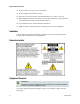
For Your Safety Explanation of Warning and Caution Icons Avoid personal injury and product damage! Do not proceed beyond any symbol until you fully understand the indicated conditions. The following warning and caution icons alert you to important information about the safe operation of this product: You may find this symbol in the document that accompanies this product. This symbol indicates important operating or maintenance instructions. You may find this symbol affixed to the product.
Notices Trademark Acknowledgments Cisco and the Cisco logo are trademarks or registered trademarks of Cisco and/or its affiliates in the U.S. and other countries. A listing of Cisco's trademarks can be found at www.cisco.com/go/trademarks. Third party trademarks mentioned are the property of their respective owners. The use of the word partner does not imply a partnership relationship between Cisco and any other company. (1009R) Publication Disclaimer Cisco Systems, Inc.
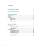
Contents Cisco DAXI Product Notices v Important Safety Instructions vii Chapter 1 Introduction 1 Product Overview .................................................................................................................... 2 In the Box .................................................................................................................................. 3 DAXI Features ...................................................................................................................
Contents Chapter 3 Operation 15 Confirming Normal Operation ............................................................................................ 16 PWR Indicator ........................................................................................................... 16 ALARM Indicator ..................................................................................................... 16 VIDEO Indicators...........................................................................................
Cisco DAXI Product Notices Cisco DAXI Product Notices System Release The DAXI is compatible with DSAN System Release 1.1.45 and greater.
Important Safety Instructions Important Safety Instructions Read and Retain Instructions Carefully read all safety and operating instructions before operating this equipment, and retain them for future reference. Follow Instructions and Heed Warnings Follow all operating and use instructions. Pay attention to all warnings and cautions in the operating instructions, as well as those that are affixed to this equipment. Terminology The terms defined below are used in this document.
Important Safety Instructions Do not work in rain, fog or snow conditions. Ensure equipment and cables are dry. Wear shoes with soles made of insulated material e.g. rubber, vinyl, etc. When making electrical connections, work with one hand in your pocket and avoid accidental contact with grounded surfaces. Use insulated tools to make electrical connections. Make all other connections before connecting power to the equipment.
Important Safety Instructions If this equipment uses AC power, place this equipment close enough to a mains AC outlet to accommodate the length of this equipment's power cord. Route all power cords so that people cannot walk on, place objects on, or lean objects against them. This may pinch or damage the power cords. Pay particular attention to power cords at plugs, outlets, and the points where the power cords exit this equipment.
Important Safety Instructions This equipment may have openings for ventilation that protect it from overheating. To ensure the reliability of this equipment, do not obstruct the openings. Do not place other equipment, lamps, books, or other objects on top of this equipment. Do not place this equipment in any of the following locations.
Important Safety Instructions Lightning and Power Surges To protect this equipment against damage from lightning storms and power-line surges, do the following where applicable: Disconnect the power cord from the grounded mains electrical outlet and disconnect the antenna or cable system under the following circumstances.
Important Safety Instructions Safety Plugs (USA Only) If this equipment uses AC power, it may be equipped with either a 3-terminal (grounding-type) safety plug or a 2-terminal (polarized) safety plug. The wide blade or the third terminal is provided for safety. Do not defeat the safety purpose of the grounding-type or polarized safety plug.
Important Safety Instructions Equipotential Bonding If this equipment is equipped with an external chassis terminal marked with the IEC 60417-5020 chassis icon ( ), the installer should refer to CENELEC standard EN 50083-1 or IEC standard IEC 60728-11 for correct equipotential bonding connection instructions. Outdoor Grounding System If this equipment connects to an outdoor antenna or cable system, be sure the antenna or cable system is grounded.
Important Safety Instructions Servicing WARNING: Avoid electric shock! Opening or removing this equipment’s cover may expose you to dangerous voltages. Do not open the cover of this equipment. Refer all servicing to qualified personnel only. Contact us for instructions. Damage that Requires Service For damage that requires service, disconnect this equipment from its electrical power source.
Important Safety Instructions Modifications This equipment has been designed and tested to comply with applicable safety, laser safety, and EMC regulations, codes, and standards to ensure safe operation in its intended environment. Refer to this equipment's data sheet for details about regulatory compliance approvals. Do not make modifications to this equipment. Any changes or modifications could void the user’s authority to operate this equipment.
Important Safety Instructions conductive connector bodies and backshells with cable clamps that are conductively bonded to the backshell and capable of making 360° connection to the cable shielding. Exceptions from this general rule will be clearly stated in the connector description for the excepted connector in question. Ethernet cables should be of the double-shielded type. Coaxial cables should be of the double-braided shielded type.
1 Chapter 1 Introduction This chapter gives an overview of the purpose, features, and operation of the Cisco DSAN Auxiliary Input Box (DAXI). In This Chapter 4035812 Rev B Product Overview................................................................................... 2 In the Box ................................................................................................. 3 DAXI Features .........................................................................................
Chapter 1 Introduction Product Overview The DAXI is an accessory for the Cisco DSAN System that converts up to four analog video channels to digital format for distribution via the DSAN. The DAXI provides baseband video and audio conversion to MPEG-2 Transport Stream (TS). The output is carried over one Asynchronous Serial Interface (ASI) channel at 270 Mbps to the DSAN Aux1 or Aux2 input port.
In the Box In the Box The DAXI ships with an external +12 VDC power supply module, as shown below.
Chapter 1 Introduction DAXI Features 4:1 baseband to MPEG-2 encoding ASI output Requires no user configuration Stackable, 1 RU profile SCTE 21 Closed Caption support Automatic Gain Control for video Integrated frame synchronizer with internal reference DAXI Front Panel The DAXI front panel contains the LED indicators and air inlets for the dual cooling fans.
DAXI Operation DAXI Operation The DAXI converts up to four auxiliary channels of analog video and audio content to a single digital data stream for input to the DSAN via its Aux1 or Aux2 input port. Both DSAN Aux ports can be active at the same time, allowing for connection of two DAXI units to support up to eight auxiliary channels. The DSAN recovers the individual content channels from the DAXI data stream and assigns them to EIA channels in accordance with its current configuration.
2 Chapter 2 Installation This chapter provides instructions for installing the DAXI in your cable system. In This Chapter 4035812 Rev B Before You Begin..................................................................................... 8 Installing the DAXI ............................................................................... 10 Connecting Cables to the DAXI ..........................................................
Chapter 2 Installation Before You Begin Before you start installing the DAXI, make sure you have all of the tools and accessories needed for installation. No tools are needed when mounting the DAXI on a shelf or countertop. Wall or rack mounting requires screwdrivers of the appropriate type and size. Wall mounting may also require tools for drilling holes into the mounting surface.
Before You Begin Housing Dimensions This illustration shows the dimensions of the DAXI unit and the power supply bracket. Use these measurements to calculate clearance requirements for your installation.
Chapter 2 Installation Installing the DAXI You can install the DAXI and its power supply in any of the following ways: On a shelf On a wall In a 19-inch equipment rack The following procedures explain how to install the DAXI using each method. Note: Wall or rack mounting requires accessory kit part number 4036620, available separately. To Install the DAXI on a Shelf Complete the following steps to install the DAXI on a shelf. 1 10 Carefully select and prepare the area to receive the DAXI.
Installing the DAXI Note: When stacking a pair of DAXI units to provide up to 8 auxiliary program channels, use the four dimples in the top of the lower unit to cradle the feet of the upper unit, as shown below. To Install the DAXI on a Wall Complete the following steps to install the DAXI and its power supply on a wall. 1 Carefully select and prepare the area to receive the DAXI unit. Consider the weight of the DAXI, DC power supply, mounting brackets, and all attached cabling.
Chapter 2 Installation 12 2 Using the wall-mounting bracket as a guide, mark the location of four screw holes in the mounting surface. Prepare the screw holes for installation as needed, possibly by drilling pilot holes or installing wall anchors. 3 Install four #8 mounting screws (not provided) in the holes. Choose a thread type suitable for the wall material, and leave the heads at least three threads from the mounting surface.
Installing the DAXI To Install the DAXI in a Rack The DAXI rack mount bracket holds one or two DAXI units and installs in a standard 19-inch equipment rack. Complete the following steps to install the DAXI in a rack. 1 Place the DAXI unit upside-down on the work surface. Note: When mounting a pair of DAXI units, lay the units side-by-side with their front panels facing the same direction and about one inch apart.
Chapter 2 Installation Connecting Cables to the DAXI All input, output, and power connections to the DAXI are made via the DAXI back panel, as shown in the following illustration. To Connect the Output Cable Insert the plug from the ASI cable in the jack labeled ASI OUT at far left on the DAXI back panel. Note: To allow for connection to an outside DSAN, the ASI output port is surge protected, and the length of the ASI cable from DAXI to DSAN can be up to 250 meters of Belden 8281 or equivalent.
3 Chapter 3 Operation Introduction This chapter provides instructions for confirming normal operation of the DAXI and for confirming the correct program output. In This Chapter 4035812 Rev B Confirming Normal Operation ........................................................... 16 Confirming Program Output ..............................................................
Chapter 3 Operation Confirming Normal Operation After installing the DAXI, confirm normal operation of the unit by checking the status of the front-panel LED indicators. PWR Indicator Check that the PWR LED is ON. This indicates that the unit is receiving +12 VDC power. ALARM Indicator Verify that the ALARM LED is OFF.
Confirming Program Output Confirming Program Output After verifying normal DAXI operation, you should confirm the quality of video and audio on each active Aux program channel. To do this, you must know which EIA channels the host DSAN uses to display Aux content. This information is often available from system records. If it is not, you can use the DSAN CLI to examine the DSAN Auxiliary Input Status page and learn which channels are used for Aux content.
Chapter 3 Operation Information displayed for PORT A1 and PORT A2 includes the following: Parameter Description Status Status for the DAXI box attached to the corresponding port; OK = in use SW Software version number Temp Temperature in degrees Celsius Fan1 or Fan2 Fan status; operational = OK Model Model number Serial Serial number Mfg Date Manufacturing date code in mm/dd/yyyy format TOS Time of service Uptime Time since last DAXI reboot For further details on using the CLI, see the
4 Chapter 4 Troubleshooting Introduction In the unlikely event of a problem with DAXI operation, use the information in this chapter to help identify and resolve the issue. In This Chapter 4035812 Rev B Troubleshooting Common Problems ................................................. 20 Alarm Troubleshooting........................................................................
Chapter 4 Troubleshooting Troubleshooting Common Problems The problems most likely to arise when operating the DAXI fall into the following categories: Unit does not power up at all Unit powers up but provides no ASI output to DSAN Unit provides ASI output but a video or audio channel is missing The information in this chapter may help in identifying and resolving these common problems. For further assistance if needed, please contact your local customer support representative.
Troubleshooting Common Problems Missing Video If a DAXI with two or more auxiliary sources connected boots up normally (PWR LED and ASI LED both ON) but the video portion of one or more channels is missing (VIDEO LED OFF), check for one or more of the following: The missing service or services are not provisioned on the DSAN. The DAXI ASI output is either not connected to the DSAN or the ASI interconnecting cable has excessive loss.
Chapter 4 Troubleshooting Alarm Troubleshooting If the DAXI ALARMS LED is ON, one or more alarm conditions may be present. When ON, this LED has two possible states: It glows red to indicate failure of both internal fans. It glows yellow to indicate failure of one internal fan, or to indicate that the operating temperature of the unit is above or below allowable operating range.
5 Chapter 5 Customer Support Information Introduction This chapter contains information on obtaining product support. Obtaining Product Support IF… THEN… you have general questions about this product contact your distributor or sales agent for product information or refer to product data sheets on www.cisco.com. you have technical questions about this product call the nearest Technical Support center. you have customer service questions call the nearest Customer Service about this product center.
Chapter 5 Customer Support Information Support Telephone Numbers This table lists the Technical Support and Customer Service numbers for your area.
Glossary A ac, AC alternating current. An electric current that reverses its direction at regularly recurring intervals. AC-3 audio compression - 3. analog channel A channel that occupies a fixed location in a 6 MHz bandwidth within the 54 MHz to 550 MHz range of the RF band. Analog video channels deliver one traditional broadcast television channel in each 6 MHz band. ASI asynchronous serial interface. Allows the intermittent transfer of data one bit at a time rather than in a steady stream.
Glossary channel map A logical element that links a service with a channel so that the service can be viewed or used by the subscriber. For example, a channel map could link The Golf Channel with channel 63 so that when subscribers tune to channel 63, they view The Golf Channel. CLI command line interface. A command reference software that allows the user to interact with the operating system by entering commands and optional arguments. CMTS Cable Modem Termination System.
Glossary dc, DC direct current. An electric current flowing in one direction only and substantially constant in value. DES data encryption standard. DHCP dynamic host configuration protocol. TCP/IP protocol that manages a pool of IP addresses. DNCS Digital Network Control System. A computer workstation that defines, organizes, monitors, and controls the components, features, and applications supported by the digital broadband delivery system. DOCSIS data over cable service interface specification.
Glossary equalizer Controls the tilt to the drop ports. It does not affect the feeder cable signal. An EQ value is selected for each installation to provide the specified output tilt. F F-connector A screw-on coaxial connector typically used inside homes or on drop cabling. FEC forward error correction.
Glossary I in-lb inch-pound. A measure of torque defined by the application of one pound of force on a lever at a point on the lever that is one inch from the pivot point. IP address Internet protocol address. A 32-bit sequence of numbers used for routing IP data. Each IP address identifies a specific component on a specific network. The address contains a network address identifier and a host identifier.
Glossary MPEG-2 Intended for higher quality video-on-demand applications and runs at data rates between 4 and 9 Mbps. MPTS Multi-program transport stream. N Nm Newton meter. A measure of torque defined by the application of one Newton of force on a lever at a point on the lever that is one meter from the pivot point. (1 Nm = 0.737561 ft-lb) node Any device, such as a DSAN unit, that is connected to a network, or a branching or exchange point. NTSC National Television Standards Committee.
Glossary phase and amplitude of carrier waves are altered to represent the binary code. By manipulating two factors, more discrete digital states are possible and therefore larger binary schemes can be represented. QAM256 A QAM technique that produces 256 discrete states, each state representing 8 bits of information. The most complex of common QAM techniques. QAM64 A QAM technique that produces 64 discrete states, each state representing 6 bits of information. QPSK quadrature phase-shift keying.
Glossary SCTE Society of Cable Telecommunications Engineers, Inc. A not-for-profit professional organization formed in 1969 to promote the sharing of operational and technical knowledge in the field of cable television and broadband communications. SI system or service information. Tuning information sent from the DNCS to DHCTs which provides the information that DHCTs need to be able to tune to a particular service. SNMP simple network management protocol.
Glossary TX transmit or transmitter. U UDSAN universal digital service access node. V V volt. VDC volts direct current. voltage electrical potential as measured in volts (V), millivolts (mV), or other related units. W W watt. A measure of electrical power required to do work at the rate of one joule per second. In a purely resistive load, 1 Watt = 1 Volt x 1 Amp.
Index A ac, AC • 25 AC-3 • 25 ALARM Indicator • 16 Alarm Troubleshooting • 22 analog channel • 25 ASI • 25 ASI Indicator • 16 attenuation • 25 DOCSIS • 27 DSAN • 27 DVB • 27 E EAS • 27 eCM • 27 EIA • 27 EQ • 27 equalizer • 28 B F baseband • 25 Before You Begin • 8 BTSC • 25 F-connector • 28 FEC • 28 forward path • 28 ft-lb • 28 C CATV • 25 channel map • 26 CLI • 26 CMTS • 26 composite video • 26 Confirming Normal Operation • 16 Confirming Program Output • 17 Connecting Cables to the DAXI • 14 Custome
Index MHz • 29 Missing Video • 21 Motorola DTA • 29 MPEG • 29 MPEG-2 • 30 MPTS • 30 Nm • 30 No ASI Output • 20 No Power-Up • 20 node • 30 NTSC • 30 To Connect Input Cables • 14 To Connect Power • 14 To Connect the Output Cable • 14 To Install the DAXI in a Rack • 13 To Install the DAXI on a Shelf • 10 To Install the DAXI on a Wall • 11 Tools and Accessories • 8 torque • 32 trap • 32 Troubleshooting • 19 Troubleshooting Common Problems • 20 TS • 32 TX • 33 O U OID • 30 Operation • 15 UDSAN • 33 P V •
5030 Sugarloaf Parkway, Box 465447 Lawrenceville, GA 30042 678 277-1120 800 722-2009 This document includes various trademarks of Cisco Systems, Inc. Please see the Notices section of this document for a list of Cisco Systems, Inc., trademarks used in this document. Product and service availability are subject to change without notice. © 2010-2011 Cisco and/or its affiliates. All rights reserved.